Terofire Products
2
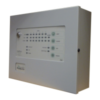
Introduction
The information provided in this manual covers the Terofire Plus range
of fire alarm control panels. The Terofire range is designed to meet the
requirements of BS5839 Parts 1 & 4 1988 and includes panels of 2, 4,
6, 8 and 12 zones.
This product should be installed, commissioned and maintained by
suitably qualified service personnel with reference to IEE regulations
and any statutory requirements.
General Description
The Terofire Plus range of fire alarm control panels are microprocessor
controlled and are available with 2-12 sense zones (detector zones).
The Terofire 12 is provided with 4 alarm zones (bell zones) while the
other panels in the range have 2 alarm zones. All Terofire Plus panels
have a one man test facility, class change input, fault output and two
sets of volt free changeover contacts which operate on fire. If a fire is
detected by a device on a sense zone, the alarm zone devices will
operate automatically and the zone that detected the fire will be
indicated on the front panel. The panel also allows the user to operate
the alarms manually.
Installation Procedure
Before proceeding with the installation, please read the section
Panel
Operation
.
Installation of the panel should be carried out by qualified
personnel.
Using the metal box as a template, mark the position of the fixing holes
on the wall. Drill and plug the wall then screw the panel to the wall.
Ensure the panel is free from knockout discs, swarf and other debris.
Do not connect any cables until after the following test is performed.
All end of line resistors should be fitted in the panel at this stage.
Connect the panel mains input to an exclusive 240V AC fused supply.
Switch the mains supply on. The internal buzzer will sound. Connect
two sealed lead acid batteries to the panel. They should be connected
in series, providing a 24V DC supply.
 Loading...