Splitband ampliers HS004, HS004L, HS004T
EN
Vers. 1.06
INSTALLATION INSTRUCTIONS
Read the product description and safety instruction rst.
Installation of system according standard IEC60728-11 ensures safety of personnel and prevents apparatus against
damaging due to lightning or other sources of overvoltage surges.
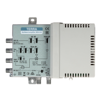
Gain of every sub-band can be adjusted with screwdriver (12). There is a possibility to adjust the gain and slope of the
amplier in every sub-band by ne turning 10 dB regulators (7, 8) and an additional 10 dB by switching switches (5, 6) in
VHF and UHF bands.
Power feed for external equipment is turned on and o by switch (9). It has short circuit and overload protection. In normal
conditions powering indicator (10) glows green. If short circuit or overload in external powered equipment is detected - glows red.
1 23
4
9
10
11
6
5
5
6
7
7
8
8
12
13
13
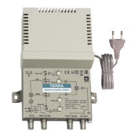
1. RF IN - RF signal input, DC output connector
2. RF OUT - RF signal output connector
3. TEST -20 dB
4. TEST -30 dB
5. gain (attenuation) switches for each sub-band
6. slope (attenuation) switches for each sub-band
7. ne tuning gain (attenuation) regulators for
each sub-band
8. slope (attenuation) ne tuning regulators for
each sub-band
9. switch to turn on/o the power feed for external
equipment
10. powering indicator
11. functional ground clamp
12. screwdriver
13. mounting supports
Product description
The splitband ampliers HS004, HS004L, HS004T are intended for amplifying cable TV, terrestrial TV and FM radio signals.
There is a possibility to adjust the gain and slope of the amplier separately in VHF and UHF bands.
The ampliers can provide power (+12 V) to external equipment through RF IN connector (1).
The UHF sub-band of the HS004L, HS004T ampliers have integrated 30 dB LTE signal suppression lter .
The housing of ampliers meets more stringent screening requirements according to EN50083-2, class A.
According to the standard ETSI EN 303 354 V.1.1.1, type of these ampliers is Launch, selectivity clasication 0.
The ampliers are intended for indoor use only.
Safety instructions
Installation of the amplier must be done according IEC60728-11 and national safety standards.
The amplier is powered from mains 230 V~. This voltage is dangerous to life.
Any repairs must be done by a skilled personnel.
Do not remove the cover of the power supply section, without disconnecting the unit from the mains supply.
Do not plug the amplier into the mains supply if the power cord or plug is damaged.
Do not plug the amplier into the mains supply until all cables have been connected correctly.
The mains socket must be easily accessible.
Avoid placing amplier next to central heating components, near highly combustible materials and in areas of high humidity.
If the amplier has been kept in cold conditions for a long time, keep it in a warm room no less than 2 hours before plugging
into the mains.
Do not insert any objects into ventilation openings;
The ventilation should not be impeded by covering the ventilation openings with items, such as newspapers, table-cloths, curtains.
Mount the amplier on not ammable wall or in not ammable installation box in vertical position with RF input connector
underneath. The amplier must be xed with steel screws Ø 4-5 mm. The screws are not included in a package. Mount in
locations where children not likely to be present. Shields of cables must be connected to main potential equalization bus.
From top, front and bottom of installed amplier must be at least 10 cm free space.
External view