9
Figure 10
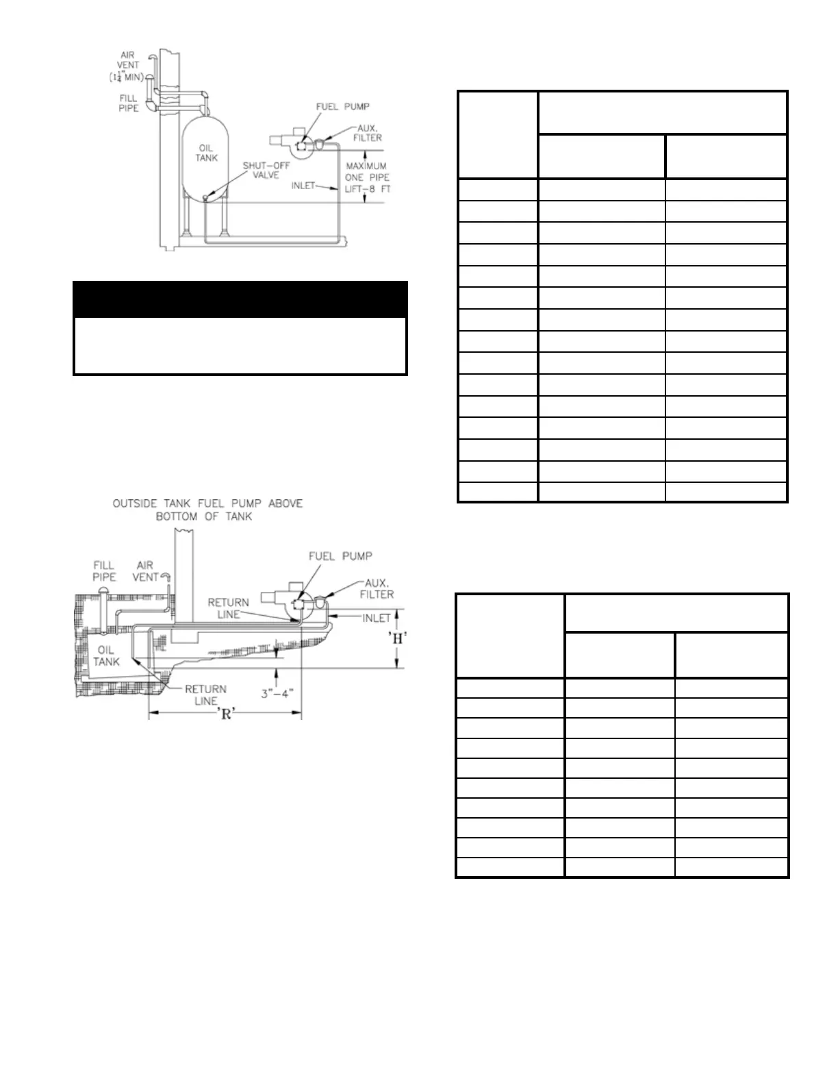
Figure 9
IMPORTANT
Single-pipe installations must be absolutely airtight
or leaks or loss of prime may result. Bleed line and
fuel unit completely.
TWO-PIPE OIL LINES - For two-pipe systems where
more lift is required, the two-stage fuel unit is
recommended. Tables 2 (single-stage) and 3 (two-stage)
show allowable lift and lengths of 3/8-inch and ½-inch
OD tubing for both suction and return lines. Refer to
Figure 10.
Be sure that all oil line connections are absolutely
airtight.
Check all connections and joints. Flared ttings are
recommended. Do not use compression ttings.
Open the air-bleed valve and start the burner. For clean
bleed, slip a 3/16” ID hose over the end of the bleed
valve and bleed into a container. Continue to bleed for
15 seconds after oil is free of air bubbles. Stop burner
and close valve.
Lift "H"
Maximum Length of Tubing
"H" + "R"
3/8" OD
Tubing (3 GPH)
1/2" OD
Tubing (3 GPH)
0' 84' 100'
1' 78' 100'
2' 73' 100'
3' 68' 100'
4' 63' 100'
5' 57' 100'
6' 52' 100'
7' 47' 100'
8' 42' 100'
9' 36' 100'
10' 31' 100'
11' 26' 100'
12' 21' 83'
13' --- 62'
14' --- 41'
TABLE 2: SINGLE-STAGE UNITS (3450 RPM)
TWO-PIPE SYSTEMS
Lift "H"
Maximum Length of Tubing
"H" + "R"
3/8" OD
Tubing (3 GPH)
1/2" OD
Tubing (3 GPH)
0' 93' 100'
2' 85' 100'
4' 77' 100'
6' 69' 100'
8' 60' 100'
10' 52' 100'
12' 44' 100'
14' 36' 100'
16' 27' 100'
18' --- 76'
TABLE 3: TWO-STAGE UNITS (3450 RPM)
TWO-PIPE SYSTEMS
 Loading...