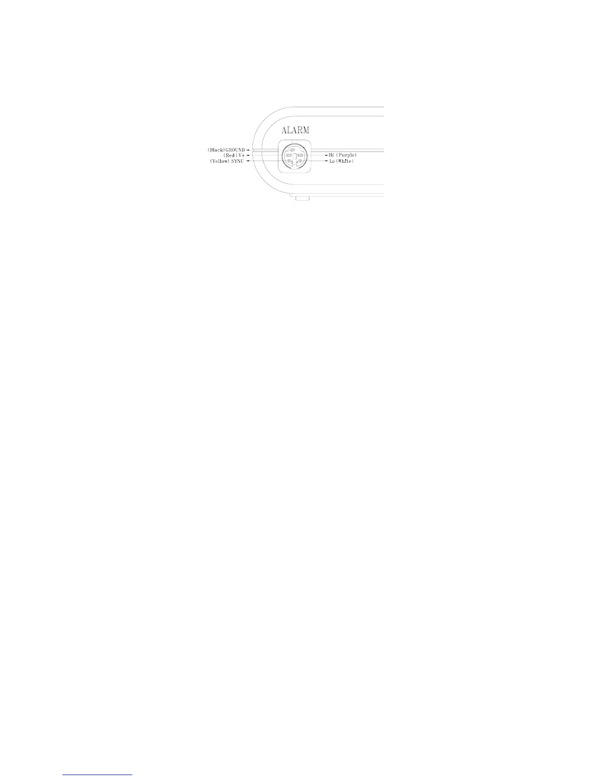
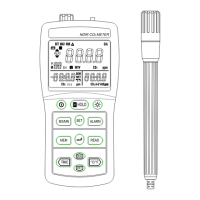
7
9. Hi/ Low Alarm output connector
:
Fig-4
Pin 1: GND ( external supply low voltage )
Pin 2: VCC ( external supply high voltage )
Pin 3: SYNC( external trigger signal )
Pin4 (HiAlarm) and pin5 (LowAlarm) signals have to be
synchronized with pin3. The pin5 and pin4 will not function
(always low) unless SYNC (pin3) is in the high state. If SYNC
is a low signal, then pin4 and pin5 will be in the low state.
Pin4
1
: HiAlarm
If the reading is higher than the high alarm point, then (pin 4)
will be in high state, otherwise, in Low state.
Pin 5
1
: LoAlarm
If the reading is lower than / equal the low alarm point, (pin 5)
will be in high state, otherwise, in low state.
1
The output of Pin 4 and 5 might delay 0.4 sec due to the A/D
scanning time in the data logger.
Description of the MINI DIN cable:
Red wire : VCC (external supply high voltage)
Black wire : GND (external supply low voltage)
Yellow : SYNC (external trigger signal)
White : HiAlarm
Purple : LowAlarm