testo 382
Instruction Manual
Digital multimeter 0590.0382
According to the conformity certificate, the
instruments meet 89/336/EEC guidelines.
The instruments were tested for EMC in the
frequency range from 150 kHz - 1MHz. The speci-
fied parameters cannot be guaranteed in the fre-
quency range from 60 MHz-190 MHz.
You can carry out the following using
testo 382:
- Measures DC and AC voltage up to
1000 V
- Measures DC and AC current
- DC current measurement up to 10 A
- Resistance measurement up to 30 MΩ
- Continuity test
Supplied:
1 x testo 382 with protection case
1 x battery 9V IEC 6LR61
2 x measuring leads with test prods (rd/bl)
1 x Instruction manual
Symbols on the instrument or in the
Instruction manual:
Caution! Warning about danger point.
Refer to Instruction manual.
Caution! Dangerous voltage
Direct current
Alternating current
Ground. Do not exceed max. voltage
range between input socket and ground.
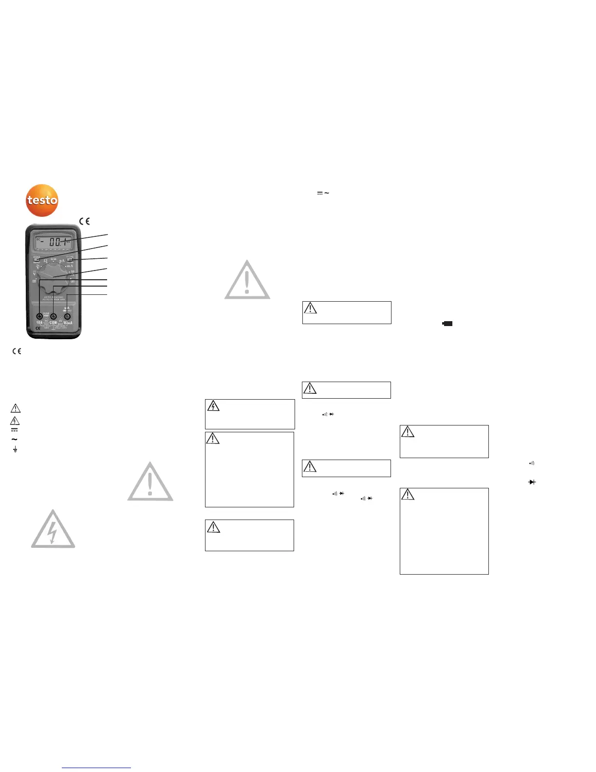
Digital display
Switch for direct current/alternating current,
continuity
Measuring range/Reading switch
Input socket “VΩmA”
Input socket “COM”
Input socket “10 A”
Data hold / Reset
Safety measures
The instrument and test prods should only
be held by the handles provided for this
purpose.
Avoid all contact with the test prods.
To change a battery or fuse, the multimeter
should only be opened by a person who is
familiar with the dangers of electric current.
Before opening, ensure that the measuring
leads are separated from the object being
measured and that the instrument is swit-
ched off.
This instrument meets the safety require-
ments in accordance with IEC-1010-1
(EN61010-1) Protection Class II and
Overvoltage category, Cat III / 600 V for
electric measuring instruments.
Contamination level 2.
These instruments should not be used in
high-energy circuits. It is suitable for mea-
surements in systems of the Overvoltage
Category III in accordance with
IEC 664 (max. 600 V AC/DC, 10 A).
Please read the Instruction manual carefully
prior to using the instrument and adhere to
the instructions given.
If instructions are not adhered to or war-
nings are ignored, serious or life-threatening
injuries to the user or damage to the instru-
ment may be the consequence.
If working with voltages greater than 120 V
(60 V) DC or 50 V (25 V) eff AC precautio-
nary measures must be adhered to in order
to avoid an electric shock. These values are
the limit for contact voltages in accordance
with DIN VDE (values in brackets apply to
medical or agricultural sectors).
Prior to every measurement, please ensure
that the measuring leads and the measuring
instrument are in perfect working order.
The measuring instrument should only be
used in the measuring ranges specified.
Never measure current in circuits with more
than 250V DC.
The measuring instrument should only be
used in mains systems which are fused to
max. 16A.
Please adhere to current accident prevention
guidelines.
Direct sunlight on the instrument should be
avoided. A perfectly functioning instrument
and a long life is guaranteed if the above
points are adhered to.
Measuring
The measuring range selection switch must
be at the required function before the test
prods are connected to the object being
measured.
Remove the measuring leads from the
object being tested before switching to a
new function or a different measuring range.
The instrument should only be used in a dry
and clean atmosphere. Dirt and moisture
reduce insulation resistances and could lead
to electric shocks in the case of high volta-
ges.
The instrument should only be used in the
measuring ranges specified.
Check if the instrument is working properly
before use (e.g. on a known current or vol-
tage source, see also DIN VDE 0105, Part
1).
Ensure that the measuring leads are in per-
fect order.
The use of makeshift fuses, in particular the
short-circuiting of fuse-carriers is not per-
mitted and may cause the measuring instru-
ment to be destroyed and cause serious
physical injury.
Never measure current in circuits
where there are voltages of more
than 250V. Only currents with max.
300mA can be measured in the "VΩmA”
socket and max. 10A in the “10A” socket.
Current measurement
Auto Off - Function
Measuring alternating current:
Press changeover switch. AC appe-
ars on the display. Switch measuring range
selection switch to “µA” or “mA”. If the cur-
rents are unknown, always start the measu-
rement in the highest measuring range and
switch to the lower respective measuring
range to achieve the highest resolution.
Measuring direct and alternating current:
1. Plug red measuring lead in the "10 A” or
“VΩmA” input sockets and the black
measuring lead in the “COM” socket.
2. Connect multimeter to item being tested
and then switch on item being tested.
3. Take reading from digital display.
The test object should be disconnec-
ted from supply. If in doubt, check
by measuring.
1. Set measurement type selection switch to
resistance measuring range "Ω".
2. Plug red measuring lead in the "VΩmA”
socket and the black measuring lead in
the "COM” socket.
3. Connect test prods to the item being
tested.
4. The resistance value can be read on the
digital display.
1. Set measurement type selection switch to
resistance measuring range "Ω".
2. Press changeover switch until the
symbol appears in the display.
3. The resistance value can be read from the
digital display. A buzzer sounds when
resistance values are < 20 Ω.
1. Set measuring range selection switch to
diode test
2. Press changeover button until
symbol appears in the display.
3. Plug the red measuring lead in the
"VΩmA” socket and the black measuring
lead in the "COM” socket.
4. Connect test prods to object being tested.
5. The drop in conducting-state voltage can
be read on the digital display.
Note:
The polarity of the test voltage at the
"VΩmA” socket is "+”.
Diode test
Resistance measurement
Maintenance
Continuity test
Measuring direct current:
Set the measuring range selection switch to
“µA” or “mA”. If the currents are unknown,
always start the measurement in the highest
measuring range and switch to the lower
respective measuring range to achieve the
highest resolution.
The instrument switches off automatically
after 15 min if not used. A buzzer sounds.
Switch on the instrument again via the “Data
hold / Reset” button.
The instrument does not require special
maintenance if operated in accordance with
the instruction manual . All work on the
instrument, apart from changing batteries or
fuses, should only be carried out by authori-
sed personnel.
Cleaning
If the instrument becomes dirty through
daily use, it can be cleaned with a damp
cloth and a mild domestic cleaning agent.
On no account should aggressive cleaning
agents or solvents be used for cleaning pur-
poses.
Regular calibration
The instrument should be calibrated by our
service department so as to maintain the
accuracy of the measured result. We recom-
mend annual calibration (Part No.
0520.2310 Multimeter Calibraiton
Certificate).
Changing the battery
If the battery symbol appears in the
top right corner of the display, the battery
should be replaced.
1. Disconnect the instrument from the cir-
cuit.
2. Switch off the instrument.
3. Open the battery compartment at the
back by unscrewing the screws.
4. Remove the empty battery.
5. Insert the new battery, type 9V IEC
6LR61, observe polarity and close the
housing.
Measurements can be carried out.
Please think of the environment. Do not
throw used batteries in domestic garbage.
Please dispose of responsibly.
Technical data
Display: ..................3-1/2 digit LCD
Analog display:........Bar display with 33
segments
Display range: ........3200 digits
Meas. range selection: Automatic
Battery status
display:....................Battery symbol
appears (<7 V)
Overvoltage
category: ................CAT III / 600 V
Contamination
level:........................2
Power supply: ........9 V IEC 6LR61
Power consumption: Approx. 2.6 mA (typical)
Dimensions (lxwxh): 160 x 80 x 40
Weight:....................286 g (with prot. case)
Operating temp.: ....0...+40 °C (0...80 %RH)
Storage temp.: -20...+60 °C (0...80%RH)
Range Resolution Accuracy
Direct current voltage (DCV)
300mV 100uV ±1.2%rdg+ 2dgts
3V 1mV ±0.5%rdg+ 2dgts
30V 10mV ±1.2%rdg+ 2dgts
300V 100mV ±1.2%rdg+ 2dgts
750V 1V ±1.5%rdg+ 2dgts
1000V 1V ±1.5%rdg+ 2dgts
Alternating current voltage (ACV)50Hz-60Hz
3V 1mV ±2.0%rdg+ 3dgts
30V 10mV ±2.0%rdg+ 3dgts
300V 100mV ±2.0%rdg+ 3dgts
750V 1V ±2.0%rdg+ 3dgts
1000V 1V ±2.0%rdg+ 3dgts
RReessiissttaannccee ((ΩΩ
) Up to 500 Ω
300Ω 0.1Ω ±1.2%rdg+ 3dgts
3kΩ 1Ω ±1.2%rdg+ 3dgts
30kΩ 10Ω ±1.2%rdg+ 3dgts
300kΩ 100Ω ±1.2%rdg+ 3dgts
3MΩ 1KΩ ±1.2%rdg+ 3dgts
30MΩ 10KΩ ±3.0%rdg+ 5dgts
Continuity Up to 500 Ω
Range Frequency Signal from
Signal 4.1 kHz <20W ± 10W
Diode Up to 500 Ω
Resolution Max. Accuracy
1mV 0.8mA ±8.0%rdg + 2dgts
DDiirreecctt ccuurrrreenntt ((DDCCAA))
300µA 0.1µA ±1.5%rdg+ 2dgts
3mA 1µA ±1.5%rdg+ 2dgts
30mA 10µA ±1.5%rdg+ 2dgts
300mA 100µA ±1.5%rdg+ 2dgts
10A 10mA ±2.5%rdg+ 2dgts
AAlltteerrnnaattiinngg ccuurrrreenntt ((AACCAA))
300µA 0.1µA ±2.0%rdg+ 4dgts
3mA 1µA ±2.0%rdg+ 4dgts
30mA 10µA ±2.0%rdg+ 4dgts
300mA 100µA ±2.0%rdg+ 4dgts
10A 10mA ±3.0%rdg+ 4dgts
Changing fuses
If a fuse has been triggered by overloading
or incorrect handling, change the fuse.
Fuse values:
Fuse 1: 250 V / 0.5 A quick-acting
Fuse 2: 250 V / 10 A slow
The use of makeshift fuses, in particular the
short-circuiting of fuse-carriers is not per-
mitted and may cause the instrument to be
destroyed and cause serious physical injury.
Maximum 1000V AC/DC should be
applied to the input sockets. The
instrument could be damaged and
the user is endangered if these limit values
are exceeded.
Voltage measurement
Remove the test prods from the object
being measured before selecting a
different measuring range.
1. Set measuring range selection switch to
direct or alternating current (depending
on the type of voltage being measured).
2. Plug the red measuring lead in the
“VΩmA” socket and the black measuring
lead in the “COM” socket.
3. Connect the test prods to the object
being measured. The reading is shown
on the digital display.
The test object should be disconnec-
ted from supply. If in doubt, check
by measuring.
The test object should be disconnec-
ted from supply. If in doubt, check
by measuring.
The battery should be removed if is
not planned to use the instrument
for a longer period of time. If the
batteries leak inside the instrument,
return the instrument to us for cleaning
and checking purposes.
Only use fuses with the specified cur-
rent and voltage values, switch-off
properties and dimensions.
1. Disconnect instrument from circuit.
2. Switch off the instrument and open the
battery compartment as described in
“Changing the battery” and remove the
battery.
3. Open the instrument by unscrewing the
screws at the back of the instrument.
4. Remove defect fuse and replace with a
new fuse, same type.
5. Put testo 382 back together again.
++ --
 Loading...