Switching on and off
Switching on/switching off press the key
Setting the zero point
The measurement values can be falsified by a change in the
position of the measuring instrument. After zeroing, the position
of the measuring instrument must not be changed. Carry out
zeroing before every measurement in order to compensate faul-
ty positioning or long-term zero-point drift.
The zero point can be set with the knob located between the pres-
sure connections. Check the zero point before each measure-
ment. Keep ambient temperature.
Measuring range changeover
Press the HI/LO key. The measuring range changes. This is dis-
played by the shifting of the decimal point. Measuring range HI is
operative on switching ON.
HOLD function
By means of the HOLD key, the indicated measured value can be
´frozen´ on the display.
The symbol appears in the display.
Cancel the Hold function by pressing the HOLD key once more.
Battery changing
The appearance of ´BAT´ indicates that the battery capacity is
exhausted.
- Open battery compartment
- Fit 9 V alkali battery (IEC 6LR61) or rechargeable battery
Ensure correct polarity !
Dispose of the used battery correctly and according to environ-
mental regulations.
Specifications
Technical data
Measuring media Instrument air or inert gases
Units mbar
(other units available on request)
Linearity, hysteresis and ± 0,2 % F.S. ± 1 Digit
repetition accuracy (measuring range HI)
± 0,5 % F.S. ± 1 Digit
(measuring range LO)
Reference temperature 22 °C
Temperature influence ± 0,05%/°C
Operating temperature 0 °C to +60 °C
Storage temperature -30 °C to +85 °C
Case protection class IP 54
Power supply 9 V block battery or rechargeable
battery IEC 6LR61
Current consumption approx.1.7 mA
Battery life approx. 250 h
Measuring rate 3 measurements / s
Display 3 1/2 digit LCD with sign
12.7 mm high
HOLD indication
LO BAT indication
Pneum. connection Hose 4/6 mm, NPT 1/8 ”
Case dimensions 152x83x34/29 mm
Weight incl. battery 250 g
* measuring ranges in bar
d = differential pressure g = relative pressure
1) max. static pressure = 7 bar
2) max. static pressure = 27 bar
Conversion factors
1 mbar = 0.1 kPa 1 mbar = 0.0145 psi
1 mbar = 1 hPa 1 mbar = 0.4015 inH2O
1 mbar = 0.0010 bar 1 mbar = 0.02953 inHg
1 mbar = 10.20 mmH2O 1 mbar = 0.7501 mmHg
Maintenance
testo 520 does not require any maintenance. It can be cleaned
with a damp cloth. Do not use cleaning agents containing solvents
!
You are recommended to have the instrument recalibrated by the
supplier at least once per year.
Fault
Measuring ranges
Fault/ Possible Remedy
Indication Cause
BAT Battery voltage Fit new battery
under 7.3 V
No indication Battery discharged Fit new battery
Battery not Check
correctly installed
Instrument Sensor ageing Recalibrate
inaccurate
Zero point not set Set zero point
Indicated value Excess pressure Dispatch
does not change applied to instrument for
pressure sensor repair
Erroneous mea- Battery discharged Fit new battery
sured value and
simultaneously BAT
1_ _ _ Display range Set permissible
exceeded measured value or
measuring range
Measuring range
(mbar) LO/HI
Type of
pressure
max. loading
capability(mbar)
Resolution
LO/HI
max. display
LO/HI
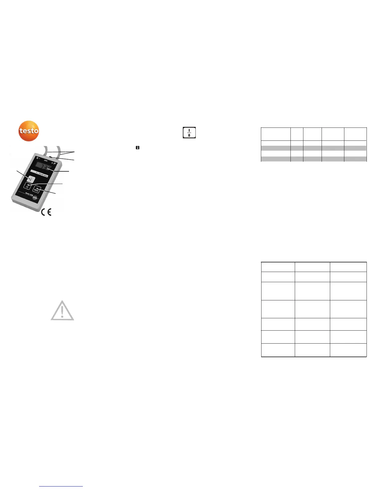
testo 520
Digital handheld pressure gauge
Description
The Testo handheld pressure gauge testo 520 is a digital pressure
measuring instrument with integrated pressure sensor for the mea-
surement of differential or relative pressures. Its 3 1/2 digit LCD
display and high precision render it suitable for a wide range of
applications.
Features
- Piezo-resistive pressure sensor
- Measuring range HI, class 0.2% F.S.
- Measuring range LO, class 0.5% F.S.
- For instrument air or non-corrosive gases
- measuring range changeover
- Large LCD display
- HOLD function
- Zero point setting
- Lo-Batt indication for battery change
- Facility for 9 V block battery or rechargeable battery
- Splash-proof ABS case (IP 54)
24 month warranty
Safety details
The pressure values in these operating instructions should not
be exceeded or the pressure sensor can be destroyed.
The instrument is not to be used in an explosive environment !
Ensure correct connection of the pneumatic hoses !
Operating
Pneumatic connections
Before making the pneumatic connection to the instrument, ensure
that no pressures can occur in the system which could exceed the
maximum overload capacity of the testo 520. The connections are
intended for direct connection to the measuring pipelines (hose,
internal diameter 4 mm, external diameter
6 mm). The 0 to 1/10 bar measuring range is always fitted with
NPT 1/8” connection unions.
P + higher pressure
- S lower pressure
Measuring instrument conform to EC directive
2004/108/EEC. The instruments were tested in the
frequency range of 27 - 500 MHz. The specified
parameters cannot be guaranteed in the named
frquency range.
On/Off
Higher/lower
measuring range
Freeze display
3 1/2 digit LCD display
Connection for pneu-
matic hoses 4/6 mm
Zero point setting
Operating instructions
0 to 20.00/200.0
1)
d,g 0.01/0.1 19.99/199.9 1500
0 to 100.0/1000
1)
d,g 0.1/1 199.9/1999 2000
0 to 200.0/2000
1)
d,g 0.1/1 199.9/1999 3000
0 to 1.000/10.00*
2)
d,g 0.001/0.01 1.999/19.99 27000
 Loading...