EasyManua.ls Logo

TEXA Konfort 700R Series - User Manual

TEXA Konfort 700R Series
175 pages
Print Icon
To Next Page IconTo Next Page
Loading...
Konfort Series 700R Service Manual TEXA Technical Assistance
I
Copyright © 2014 – TEXA S.p.A.
TABLE OF CONTENTS
INTRODUCTION 1
GENERAL SAFETY .
2
CHAPTER 1 COMPARISON BETWEEN R1234yf AND R134a
REFRIGERANTS
4
1.1 Introduction to the Greenhouse Effect 4
1.2 The Directive 2006/40/CE
4
1.3 Features of the new refrigerant R1234yf 5
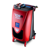
1.4 The TEXA solution: Konfort series 700R 7
CHAPTER 2 GENERAL WORKING PRINCIPLE . 9
2.1 Introduction 9
2.2 Detailed description of the single phases 11
2.2.1 Refrigerant Recovery 11
2.2.2 Oil Drain 13
2.2.3 Vacuum 13
2.2.4 Leak Test 15
2.2.5 Oil Injection 15
2.2.6 UV Injection 16
2.2.7 Refrigerant Injection 17
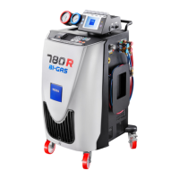
2.3 The Evolution of the BiGas management: refrigerant recovery
and injection into Konfort 780R units
18
2.3.1 Recovery of R134a refrigerant 18
2.3.2 Recovery of R1234yf refrigerant 20
2.3.3 Refrigerant R134a injection 22
2.3.4 Refrigerant R1234yf injection 23
2.4 Refrigerant Recovery on Konfort 705R 24
CHAPTER 3 KONFORT SERIES 700R: NEW ARCHITECTURE OF
THE MENU
26
3.1 Konfort 705R, 710R, 720R: Text menu on blue LCD display
26
3.1.1 The AC maintenance menu
27
3.1.2 The Additional functions menu 28
3.1.3 The Settings menu 29
3.1.4 The Service menu 30
3.2 Konfort 760R, 760R Bus and 780R BiGas: Graphic menu on
color display
31
3.2.1 The AC maintenance menu
32
3.2.2 The Additional functions menu 33
3.2.3 The Settings menu
36
3.2.4 The Service menu 37
CHAPTER 4 THE SERVICE MENU . 38
4.1 The Service menu
38
4.2 The POWER OUTPUTS function on K705R, K710R, K720R 42
4.3 The POWER OUTPUTS function on Konfort 760R, 760R Bus or
780R BiGas
48
4.4 The SENSOR CALIBRATION function on K705R, K710R, K720R 52
4.4.1 REFRIGERANT calibration on K705R, K710R and K720R 52
4.4.2 UV ADDITIVE calibration on K710R and K720R 58
4.4.3 NEW OIL calibration on K705R, K710R and K720R 58
4.4.4 MAIN SENSOR calibration on K705R, K710R and K720R 58

Table of Contents

Questions and Answers

Summary

Introduction to Konfort 700 R Service Manual

General Safety Precautions for Konfort 700 R

Chapter 1: R1234 yf vs R134 a Refrigerant Comparison

1.1 Introduction to Greenhouse Effect

Explains the natural principle of the greenhouse effect and its role in life on Earth.

1.2 EU Directive 2006;40;CE on Refrigerants

Details the EU directive mandating the use of refrigerants with low GWP from 2011.

1.3 Features of R1234 yf Refrigerant

Highlights environmental, toxicity, performance, and flammability features of R1234yf.

1.4 TEXA Konfort Series 700 R Solution

Introduces the Konfort 700R series as TEXA's solution for new refrigerant handling.

Chapter 2: General Working Principle of Konfort Units

2.1 Operating Cycle Introduction

Provides a general overview of the Konfort A/C recharging unit's operating cycle.

2.2 Detailed Description of Single Phases

Explains each phase of the Konfort equipment's operating cycle in detail.

2.3 BiGas Management in Konfort 780 R

Discusses the BiGas management for simultaneous handling of R134a and R1234yf.

2.4 Refrigerant Recovery on Konfort 705 R

Describes the refrigerant recovery process specific to Konfort 705R units.

Chapter 3: Konfort Series 700 R Menu Architecture

3.1 Konfort 705 R;710 R;720 R Text Menu

Details the menu structure and navigation for Konfort 705R, 710R, and 720R units.

3.2 Konfort 760 R;760 R Bus;780 R BiGas Graphic Menu

Explains the graphical menu interface for Konfort 760R, 760R Bus, and 780R BiGas units.

Chapter 4: The Service Menu and Functions

4.1 Service Menu Access and Levels

Describes accessing the Service menu with user and dealer passwords.

4.2 Power Outputs Functionality (K705 R;K710 R;K720 R)

Explains manual actuator activation and sensor readings for K705R, K710R, K720R.

4.3 Power Outputs Functionality (760 R Series)

Details manual actuator activation and sensor readings for Konfort 760R, 760R Bus, 780R BiGas.

4.4 Sensor Calibration (K705 R;K710 R;K720 R)

Guides through sensor calibration procedures for K705R, K710R, K720R units.

4.5 Sensor Calibration (760 R Series)

Guides through sensor calibration procedures for Konfort 760R, 760R Bus, 780R BiGas units.

4.6 Private Parameters Configuration

Allows checking and modifying reserved functional parameters of the equipment.

4.7 Public Parameters Configuration

Allows checking and modifying standard functional parameters of the equipment.

4.8 Calibration Status Overview

Provides an overview of the calibration status of each sensor.

4.9 Select Refrigerant Type

Allows selection of the refrigerant type (R134a or R1234yf) for unit operation.

4.10 Stored Errors History

Displays the history of unit functioning faults and allows deletion of errors.

4.11 Default Parameters Restoration

Allows restoring the unit's working parameters to their default values.

4.12 Customised Service Options

Enables customized settings for AC maintenance, including UV injection, DB region, and vacuum modes.

Chapter 5: Ordinary Maintenance Procedures

5.1 Main Filter Replacement

Details the procedure for replacing the main filter when automatically requested by the unit.

5.2 Vacuum Pump Oil Replacement

Explains the procedure for replacing vacuum pump oil when requested by the unit.

Chapter 6: Software Update Procedures

6.1 Manual Software Update via SD Card

Guides manual software updates using files downloaded from the Service Code website.

6.2 Automatic Software Update with Konfort 700 Updater

Describes automatic software updates using the Konfort 700 Updater PC program.

Chapter 7: Troubleshooting Guide

7.1 Troubleshooting Introduction

Introduces troubleshooting by analyzing sensors, load cells, and pressure transducers.

7.2 Equipment Does Not Switch On

Diagnoses power-on issues, checking cables, fuses, and voltage.

7.3 Display Visualization Errors

Troubleshoots display issues, checking SD card, software, and backlight.

7.4 Unit Does Not Recover Refrigerant

Troubleshoots refrigerant recovery issues, checking connections, valves, filters, and compressor.

7.5 Unit Does Not Perform Vacuum

Diagnoses vacuum phase problems, checking pump start, valves, and vacuum levels.

7.6 Unit Does Not Inject Oil

Troubleshoots oil injection failures, checking bottle connections, o-rings, and load cells.

7.7 Unit Does Not Inject UV Additive

Diagnoses UV additive injection issues, checking bottle connections and solenoid valves.

7.8 Over-Injection of Oil;UV Additive

Addresses problems with over-injection of oil or UV additive.

7.9 Equipment Does Not Inject Refrigerant

Troubleshoots refrigerant injection failures, checking tank valves, refrigerant quantity, and solenoid valves.

7.10 Unit Injects Large Refrigerant Amount

Diagnoses issues where the unit injects more refrigerant than intended.

7.11 Recovered Oil Not Discharged Correctly

Troubleshoots issues with recovered oil not draining correctly.

7.12 Main Load Cell Calibration Fault

Guides on recalibrating the main load cell and troubleshooting calibration faults.

7.13 Auxiliary Load Cells Calibration Issues

Details calibration procedures for auxiliary load cells.

7.14 Main Pressure Sensor Calibration Fault

Guides on calibrating the main pressure sensor and troubleshooting faults.

Appendix 1: Spare Parts Portal Information

Appendix 2: Electrical and Signal Connections

Konfort 705 R Connections

Shows actuator connections to the ACE Power board for Konfort 705R.

Konfort 710 R Connections

Illustrates actuator connections to the ACE Power board for Konfort 710R.

Konfort 720 R Connections

Depicts actuator connections to the ACE Power board for Konfort 720R.

Konfort 760 R;760 R Bus Connections

Shows actuator connections to the ACE Power board for Konfort 760R and 760R Bus.

Konfort 780 R BiGas Connections

Illustrates actuator connections to the ACE Power board for Konfort 780R BiGas.

Appendix 3: Flow Diagrams

Konfort 705 R Flow Diagram

Provides the flow diagram for the Konfort 705R unit.

Konfort 710 R;720 R Flow Diagrams

Shows the flow diagram for Konfort 710R and 720R units.

Konfort 760 R;760 R Bus Flow Diagrams

Presents the flow diagram for Konfort 760R and 760R Bus units.

Konfort 780 R BiGas Flow Diagram

Provides the flow diagram for the Konfort 780R BiGas unit.

Appendix 4: Solenoid Valves Location

Konfort 705 R Solenoid Valve Locations

Shows solenoid valve locations on the Konfort 705R.

Konfort 710 R;720 R Solenoid Valve Locations

Illustrates solenoid valve locations on Konfort 710R and 720R.

Konfort 760 R;760 R Bus Solenoid Valve Locations

Shows solenoid valve locations on Konfort 760R and 760R Bus.

Konfort 780 R BiGas Solenoid Valve Locations

Depicts solenoid valve locations on Konfort 780R BiGas.

TEXA Konfort 700R Series Specifications

General IconGeneral
BrandTEXA
ModelKonfort 700R Series
CategoryDiagnostic Equipment
LanguageEnglish

Related product manuals