AM1808
SPRS653E –FEBRUARY 2010–REVISED MARCH 2014
www.ti.com
6.13.3 MMC/SD Electrical Data/Timing
Table 6-40 through Table 6-41 assume testing over recommended operating conditions.
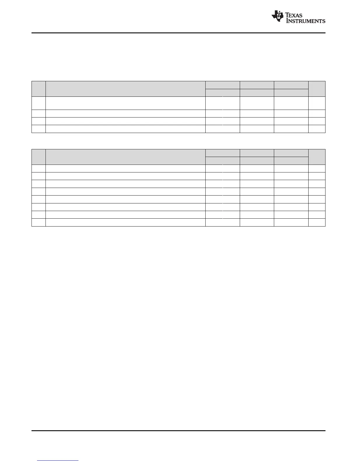
Table 6-40. Timing Requirements for MMC/SD
(see Figure 6-25 and Figure 6-27)
1.3V, 1.2V 1.1V 1.0V
NO. UNIT
MIN MAX MIN MAX MIN MAX
t
su(CMDV-
1 Setup time, MMCSD_CMD valid before MMCSD_CLK high 4 4 6 ns
CLKH)
2 t
h(CLKH-CMDV)
Hold time, MMCSD_CMD valid after MMCSD_CLK high 2.5 2.5 2.5 ns
3 t
su(DATV-CLKH)
Setup time, MMCSD_DATx valid before MMCSD_CLK high 4.5 5 6 ns
4 t
h(CLKH-DATV)
Hold time, MMCSD_DATx valid after MMCSD_CLK high 2.5 2.5 2.5 ns
Table 6-41. Switching Characteristics for MMC/SD (see Figure 6-24 through Figure 6-27)
1.3V, 1.2V 1.1V 1.0V
NO. PARAMETER UNIT
MIN MAX MIN MAX MIN MAX
7 f
(CLK)
Operating frequency, MMCSD_CLK 0 52 0 50 0 25 MHz
8 f
(CLK_ID)
Identification mode frequency, MMCSD_CLK 0 400 0 400 0 400 KHz
9 t
W(CLKL)
Pulse width, MMCSD_CLK low 6.5 6.5 10 ns
10 t
W(CLKH)
Pulse width, MMCSD_CLK high 6.5 6.5 10 ns
11 t
r(CLK)
Rise time, MMCSD_CLK 3 3 10 ns
12 t
f(CLK)
Fall time, MMCSD_CLK 3 3 10 ns
13 t
d(CLKL-CMD)
Delay time, MMCSD_CLK low to MMCSD_CMD transition -4 2.5 -4 3 -4 4 ns
14 t
d(CLKL-DAT)
Delay time, MMCSD_CLK low to MMCSD_DATx transition -4 3.3 -4 3.5 -4 4 ns
126 Peripheral Information and Electrical Specifications Copyright © 2010–2014, Texas Instruments Incorporated
Submit Documentation Feedback
Product Folder Links: AM1808