3
2
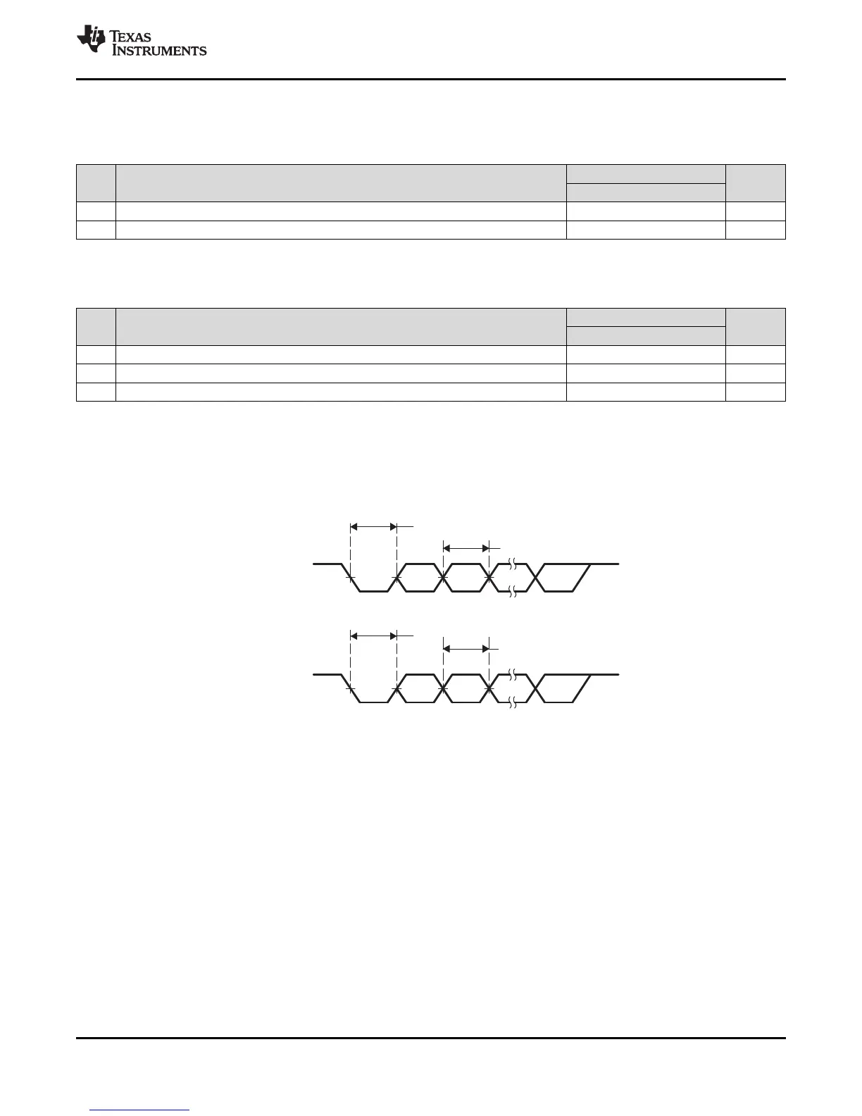
Start
Bit
Data Bits
UART_TXDn
UART_RXDn
5
Data Bits
Bit
Start
4
AM1808
www.ti.com
SPRS653E –FEBRUARY 2010–REVISED MARCH 2014
6.19.2 UART Electrical Data/Timing
Table 6-88. Timing Requirements for UART Receive
(1)
(see Figure 6-43)
1.3V, 1.2V, 1.1V, 1.0V
NO. UNIT
MIN MAX
4 t
w(URXDB)
Pulse duration, receive data bit (RXDn) 0.96U 1.05U ns
5 t
w(URXSB)
Pulse duration, receive start bit 0.96U 1.05U ns
(1) U = UART baud time = 1/programmed baud rate.
Table 6-89. Switching Characteristics Over Recommended Operating Conditions for UARTx Transmit
(1)
(see Figure 6-43)
1.3V, 1.2V, 1.1V, 1.0V
NO. PARAMETER UNIT
MIN MAX
1 f
(baud)
Maximum programmable baud rate D/E
(2) (3)
MBaud
(4)
2 t
w(UTXDB)
Pulse duration, transmit data bit (TXDn) U - 2 U + 2 ns
3 t
w(UTXSB)
Pulse duration, transmit start bit U - 2 U + 2 ns
(1) U = UART baud time = 1/programmed baud rate.
(2) D = UART input clock in MHz.
For UART0, the UART input clock is SYSCLK2.
For UART1 or UART2, the UART input clock is ASYNC3 (either PLL0_SYCLK2 or PLL1_SYSCLK2).
(3) E = UART divisor x UART sampling rate. The UART divisor is set through the UART divisor latch registers (DLL and DLH). The UART
sampling rate is set through the over-sampling mode select bit (OSM_SEL) of the UART mode definition register (MDR).
(4) Baud rate is not indicative of data rate. Actual data rate will be limited by system factors such as EDMA loading, EMIF/DDR loading,
system frequency, etc.
Figure 6-43. UART Transmit/Receive Timing
Copyright © 2010–2014, Texas Instruments Incorporated Peripheral Information and Electrical Specifications 177
Submit Documentation Feedback
Product Folder Links: AM1808