AM1808
SPRS653E –FEBRUARY 2010–REVISED MARCH 2014
www.ti.com
6.29.2 Enhanced Pulse Width Modulator (eHRPWM) Timing
PWM refers to PWM outputs on eHRPWM1-6. Table 6-126 shows the PWM timing requirements and
Table 6-127, switching characteristics.
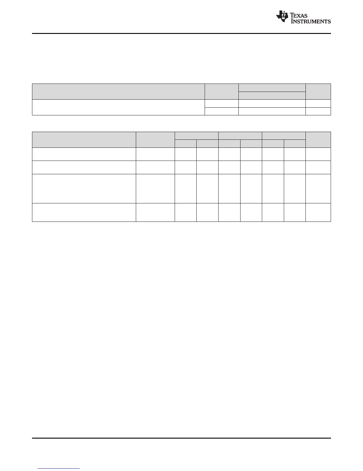
Table 6-126. Timing Requirements for eHRPWM
TEST 1.3V, 1.2V, 1.1V, 1.0V
UNIT
CONDITIONS
MIN MAX
t
w(SYNCIN)
Sync input pulse width Asynchronous 2t
c(SCO)
cycles
Synchronous 2t
c(SCO)
cycles
Table 6-127. Switching Characteristics Over Recommended Operating Conditions for eHRPWM
PARAMETER TEST 1.3V, 1.2V 1.1V 1.0V UNIT
CONDITIONS
MIN MAX MIN MAX MIN MAX
t
w(PWM)
Pulse duration, ns
20 20 26.6
PWMx output high/low
t
w(SYNCOUT)
Sync output cycles
8t
c(SCO)
8t
c(SCO)
8t
c(SCO)
pulse width
t
d(PWM)TZA
Delay time, trip input no pin load; no ns
active to PWM forced high additional
Delay time, programmable 25 25 25
trip input active to PWM delay
forced low
t
d(TZ-PWM)HZ
Delay time, no additional ns
trip input active to PWM Hi-Z programmable 20 20 20
delay
234 Peripheral Information and Electrical Specifications Copyright © 2010–2014, Texas Instruments Incorporated
Submit Documentation Feedback
Product Folder Links: AM1808