AM1808
www.ti.com
SPRS653E –FEBRUARY 2010–REVISED MARCH 2014
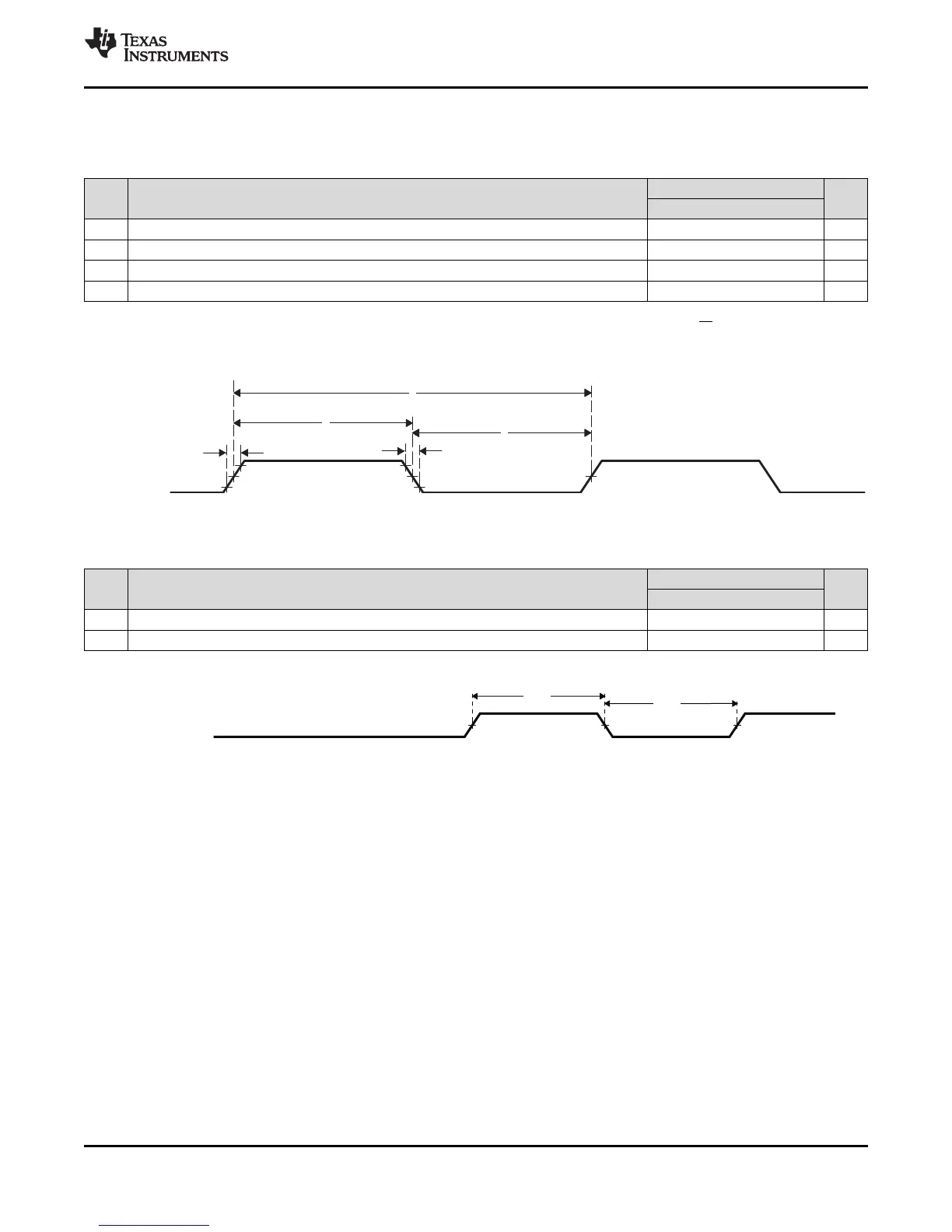
6.30.1 Timer Electrical Data/Timing
Table 6-130. Timing Requirements for Timer Input
(1) (2)
(see Figure 6-80)
1.3V, 1.2V, 1.1V, 1.0V
NO. UNIT
MIN MAX
1 t
c(TM64Px_IN12)
Cycle time, TM64Px_IN12 4P ns
2 t
w(TINPH)
Pulse duration, TM64Px_IN12 high 0.45C 0.55C ns
3 t
w(TINPL)
Pulse duration, TM64Px_IN12 low 0.45C 0.55C ns
4 t
t(TM64Px_IN12)
Transition time, TM64Px_IN12 0.05C or 10
(3)
ns
(1) P = OSCIN cycle time in ns.
(2) C = TM64P0_IN12 cycle time in ns. For example, when TM64Px_IN12 frequency is 27 MHz, use C = 37.037 ns
(3) Whichever is smaller. P = the period of the applied signal. Maintaining transition times as fast as possible is recommended to improve
noise immunity on input signals.
Figure 6-80. Timer Timing
Table 6-131. Switching Characteristics Over Recommended Operating Conditions for Timer Output
(1)
1.3V, 1.2V, 1.1V, 1.0V
NO. PARAMETER UNIT
MIN MAX
5 t
w(TOUTH)
Pulse duration, TM64P0_OUT12 high 4P ns
6 t
w(TOUTL)
Pulse duration, TM64P0_OUT12 low 4P ns
(1) P = OSCIN cycle time in ns.
Figure 6-81. Timer Timing
Copyright © 2010–2014, Texas Instruments Incorporated Peripheral Information and Electrical Specifications 237
Submit Documentation Feedback
Product Folder Links: AM1808