AM1808
www.ti.com
SPRS653E –FEBRUARY 2010–REVISED MARCH 2014
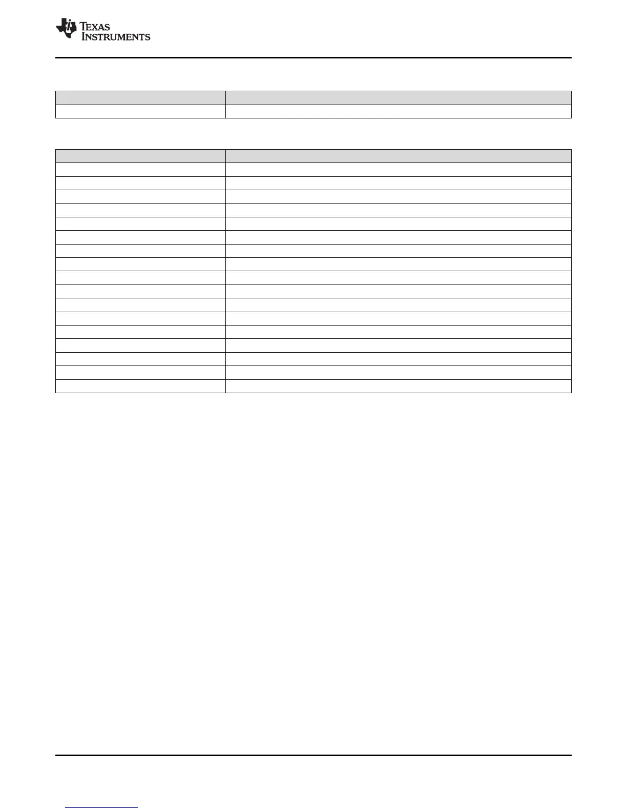
Table 3-32. Unused RTC Signal Configuration (continued)
SIGNAL NAME Configuration
RTC_VSS VSS
Table 3-33. Unused DDR2/mDDR Controller Signal Configuration
SIGNAL NAME Configuration
(1)
DDR_D[15:0] No Connect
DDR_A[13:0] No Connect
DDR_CLKP No Connect
DDR_CLKN No Connect
DDR_CKE No Connect
DDR_WE No Connect
DDR_RAS No Connect
DDR_CAS No Connect
DDS_CS No Connect
DDR_DQM[1:0] No Connect
DDR_DQS[1:0] No Connect
DDR_BA[2:0] No Connect
DDR_DQGATE0 No Connect
DDR_DQGATE1 No Connect
DDR_ZP No Connect
DDR_VREF No Connect
DDR_DVDD18 No Connect
(1) The DDR2/mDDR input buffers are enabled by default on device power up and a maximum current draw of 25mA can result on the 1.8V
supply. To minimize power consumption, the DDR2/mDDR controller input receivers should be placed in power-down mode by setting
VTPIO[14] = 1.
Copyright © 2010–2014, Texas Instruments Incorporated Device Overview 59
Submit Documentation Feedback
Product Folder Links: AM1808