7.2 PC Interface Connection
8 Operation
8.1 Starting the Program
www.ti.com
Operation
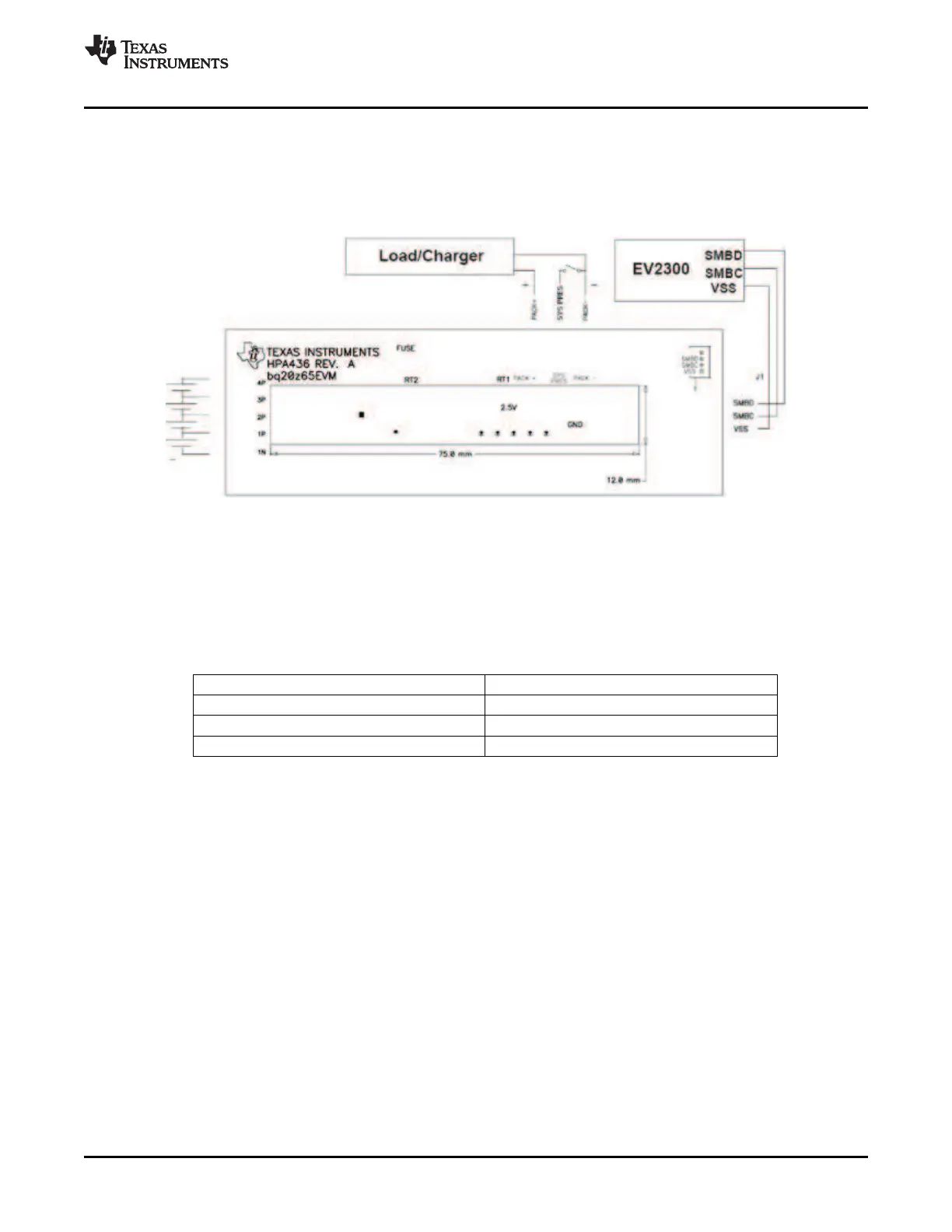
1. 4-Cell Pack: 1N (BAT–), 1P, 2P, 3P, and 4P (see Section 2.1 for definitions).
2. 3-Cell Pack: 1N (BAT–), 1P, 2P, and then connect 4P and 3P together.
3. 2-Cell Pack: 1N (BAT–), 1P, and then connect 4P, 3P, and 2P together
To start charge or discharge test, connect PRES pin to PACK- pin to set SYS PRES state. To test sleep
mode, disconnect the SYS PRES pin.
Figure 7. bq20z65 Circuit Module Connection to Cells and System Load/Charger
The following steps configure the hardware for interface to the PC:
1. Connect the bq20z65-based smart battery to the EV2300 using wire leads as shown in Table 5 .
Table 5. Circuit Module to EV2300 Connections
bq20z65-Based Battery EV2300
SMBD SMBD
SMBC SMBC
VSS GND
2. Connect the PC USB cable to the EV2300 and the PC USB port.
The bq20z65EVM-001 is now set up for operation.
This section details the operation of the bq20z65 EVSW software.
Run bq Evaluation Software from the Start | Programs | Texas Instruments | bq20z65 EVSW menu
sequence. The SBS Data screen (Figure 8 ) appears. Data begins to appear once the < Refresh> (single
time scan) button is clicked, or when the < Keep Scanning> check box is checked. To disable the scan
feature, deselect < Keep Scanning>.
The continuous scanning period can be set via the | Options | and | Set Scan Interval | menu selections.
The range for this interval is 0 ms to 65535 ms. Only items that are selected for scanning are scanned
within this period.
SLUU353 – June 2009 bq20z65EVM-001 SBS 1.1 Impedance Track™ Technology 9
Enabled Battery Management Solution Evaluation Module
Submit Documentation Feedback
 Loading...


