Design Note
DN022
SWRA215E Page 5 of 8
Note that the FREND1, FIFOTHR, TEST2, and TEST1 register settings change for different
RX filter bandwidths.
FREND1:
RX filter bandwidth > 101 kHz, FREND1 = 0xB6
RX filter bandwidth ≤ 101 kHz, FREND1 = 0x56
TEST2:
RX filter bandwidth > 325 kHz, TEST2 = 0x88
RX filter bandwidth ≤ 325 kHz, TEST2 = 0x81
TEST1:
RX filter bandwidth > 325 kHz, TEST1 = 0x31
RX filter bandwidth ≤ 325 kHz, TEST1 = 0x35
FIFOTHR:
RX filter bandwidth > 325 kHz, FIFOTHR = 0x07
RX filter bandwidth ≤ 325 kHz, FIFOTHR = 0x47
3.3 Procedure for Finding OOK/ASK Settings using SmartRF
®
Studio
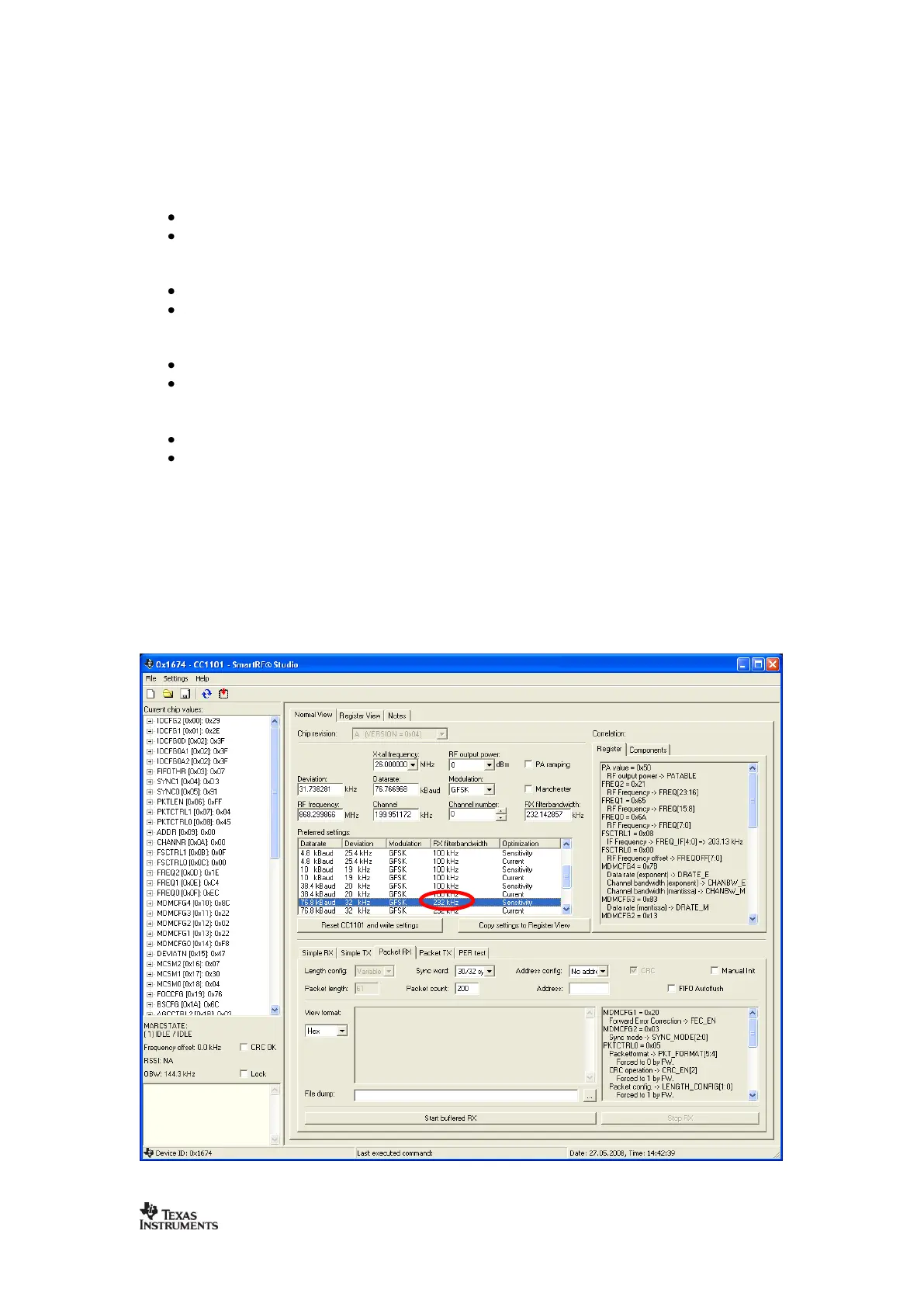
As an example, assume 4.8 kBaud data rate and 203 kHz RX filter bandwidth.
1) Use SmartRF
®
Studio to find the optimum IF frequency. Select the preferred setting that
has an RX filter bandwidth equal to the wanted bandwidth. If the wanted RX filter bandwidth is
not given by one of the preferred settings, chose the first RX filter bandwidth that is wider than
the wanted bandwidth. For a 203 kHz wanted RX filter bandwidth, select the 232 kHz RX filter
bandwidth for optimum IF frequency.

 Loading...

