Functional Unit Hazards
6-39
TMS320C67x Pipeline
6.3.6 16 16-Bit Multiply Instructions
The 16 16-bit multiply instructions use both the E1 and E2 phases of the
pipeline to complete their operations (see Table 6–21). Figure 6–10 shows the
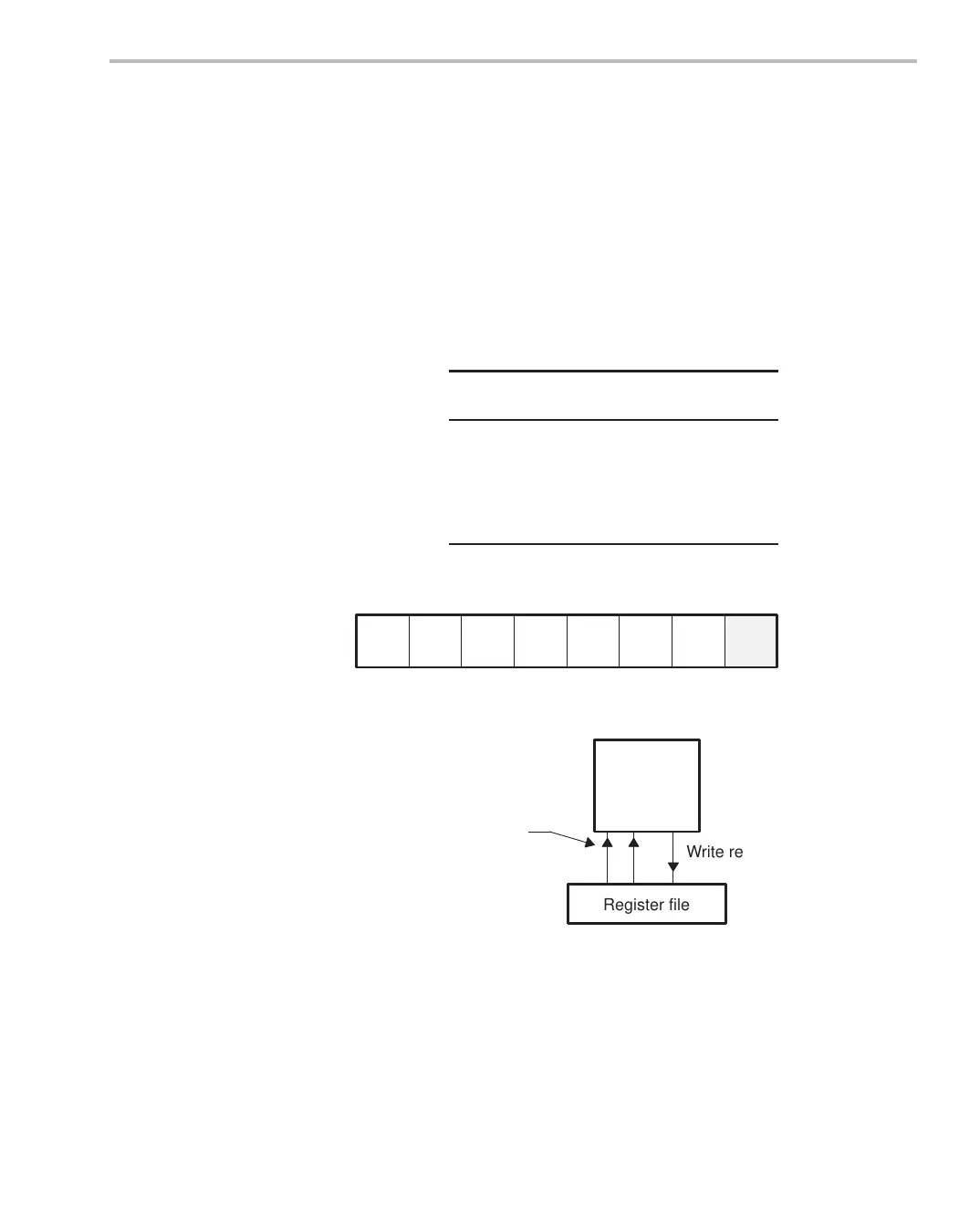
pipeline phases the multiply instructions use. Figure 6–11 shows the opera-
tions occurring in the pipeline for a multiply. In the E1 phase, the operands are
read and the multiply begins. In the E2 phase, the multiply finishes, and the
result is written to the destination register. Multiply instructions have one delay
slot.
Table 6–21. 16
16-Bit Multiply Execution
Pipeline
Stage
E1 E2
Read
src1
src2
Written
dst
Unit in use .M
Figure 6–10. Multiply Instruction Phases
PG PS PW PR DP DC E1 E2
1
delay
slot
Figure 6–11.Multiply Execution Block Diagram
(data)
Operands
Register file
Write results
Functional
unit
.M
E1
E2
 Loading...