de cómo esté conectado:
Bloqueo conectado a Conexión Positiva (SW+, Set+): Los LED se desactivan
mientras el sistema está conectado. Todos los detectores que se hayan
disparado mientras el sistema está conectado tendrán el LED de aviso
encendido de manera permanente (hasta que se desconecte el sistema). Se
puede volver a conectar los detectores subiendo y volviendo a bajar la línea
de bloqueo.
Bloqueo conectado a Alarma Positiva (AL+, A+ve): El primer detector activado
mientras el sistema esté conectado lo indicará mediante un LED de aviso que
parpadea lentamente (hasta que se desconecte el sistema). Los detectores
que se activen posteriormente lo indicarán mediante un LED de aviso
permanente. Se puede volver a conectar los detectores subiendo y volviendo
a bajar la línea de bloqueo.
Información relativa a las normativas
Proveedor: Texecom Ltd, St. Crispin Way, Haslingden, Lancashire, BB4 4PW, UK.
Grado de seguridad: EN Grado 2
Clase medioambiental: Clase II
Certicado: EN 50131-2-2
Directivas europeas
2004/108/CE (directiva CE): Por la cual, Texecom declara que este dispositivo
cumple con los requisitos esenciales y otras provisiones relevantes de la
Directiva 2004/108/EC.
R&TTE Directive: 1999/5/EC
2002/95/CE (directiva RoHS): Por la cual, Texecom declara que este
dispositivo no contiene plomo, mercurio, cadmio, cromo hexavalente,
bifenilos polibromados (PBB) o éteres de polibromodifenilos (PBDE) en un
porcentaje mayor del especicado por la Directiva europea 2002/95/EC, con
excepción de la exención que aparece en el anexo de la Directiva europea
2002/95/EC.
2002/96/CE (directiva WEEE): Los productos marcados con este símbolo no se
pueden desechar como residuos municipales no clasicados en la
Unión Europea. Al comprar un equipo nuevo equivalente, devuelva este
producto a su proveedor local o deséchelo en los puntos de recogida
designados a tal efecto a n de ayudar a un proceso de reciclaje
adecuado. Para más información consulte: www.recyclethis.com.
Mantenimiento: Debe probarse anualmente por el instalador.
Garantía: Garantía de sustitución de 5 años
El Premier 360 DT no es un sistema de alarma completo, es únicamente una
pieza. Por lo que Texecom no acepta responsabilidad alguna de cualquier
daño que se atribuya como resultado de un funcionamiento incorrecto del
detector de PIR Premier 360 DT.
Texecom se reserva el derecho a cambiar la especicación sin previo aviso.
Contact information: www.texe.com
1 2
3
6
7
Specications
Detector PIR
Signal processing DSP
Range Coverage diameter 9.3m at 3.6m
mounting height
Optics Fresnel lens
Power supply 9 to 15 V
DC (15VDC nominal @
10.6mA) Power rating: 0.16W
Peak-to-peak ripple 2 V (at 12 V
DC)
Power supply unit Rated 94HB
Startup time 60 s
Maximum current
Normal 8.7 mA
Alarm 7.5 mA
Maximum 28 mA
Mounting height 2.4 to 3.6 m
Target speed range 30 cm/s to 3 m/s (1 ft./s to 10
ft./s)
Alarm relay <24 V
DC, 50 mA, NC, resistive
load 34 Ω max.
Tamper relay <24 V
DC, 50 mA, NC
Alarm time >2 s
Dimensions (W × H × D) 116 x 33 × 116 mm
Weight 125 g
Operating environment
Temperature −35 to +55°C (-31 to 130°F)
Relative humidity 0 to 95% noncondensing
Frequency 24GHz
Maintenance Yearly test by installer
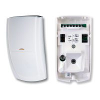
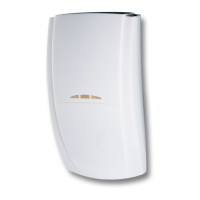
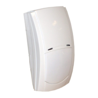
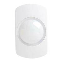
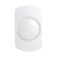
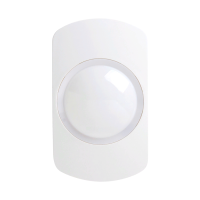
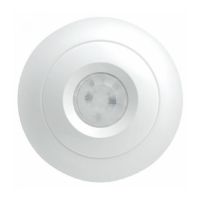
Description
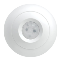
The Premier 360 DT is a ceiling mount PIR detector, which is designed to
detect a movement of an intruder, and to activate an alarm on a control panel.
The product must be connected to a listed burglar system compatible control
unit or power supply unit, which provides a supply voltage between 9 and 15
VDC as well as a minimum 4 hours of standby power.
The Premier 360 DT is not suitable for outdoor use.
Figure legends
Item Description Item Description
Fig 2 Fig. 5
1. Cable entry 1. Tamper relay
2. Screw 2. Alarm relay
3. Supply connector for 0 V and
12 V
4. First to Alarm/Latch Input
5. Remote LED
Fig 3 Fig 6
1. Tamper jumper 1. Selectable EOL conguration
2. Alarm jumper 2. Double Pole (jumper links
not used)
3. LED jumper 3. Dual End-of-Line (DEOL)
4. Pulse count jumper
5. Pulse Count 1
6. Pulse Count 2
Installation guidelines
The technology used in these detectors resists false alarm hazards. However,
avoid potential causes of instability such as:
• Direct sunlight on the detector.
• Heat sources within the detector eld of view.
• Strong draughts onto the detector.
• Large animals within the detector eld of view.
• Obscuring the detector eld of view with large objects, such as furniture.
EN: Installation Sheet
Regulatory information
Supplier:Texecom Ltd, St. Crispin Way, Haslingden, Lancashire, BB4 4PW, UK.
Security grade: EN Grade 2
Environmental class: Class II
Standards: EN 50131-2-2
European Directives
2004/108/EC (CE directive): Hereby, Texecom declares that this device is in
compliance with the essential requirements and other relevant provisions of
Directive 2004/108/EC.
R&TTE Directive: 1999/5/EC
2002/95/EC (RoHS Directive): Hereby, Texecom declares that this device does
not contain lead, mercury, cadmium, hexavalent chromium, polybrominated
biphenyls (PBB) or polybrominated depheny ethers (PBDE) in more than the
percentage specied by EU directive 2002/95/EC, except exemptions stated in
EU directive 2002/95/EC annex.
2002/96/EC (WEEE directive): Products marked with this symbol cannot be
disposed of as unsorted municipal waste in the European Union.
For proper recycling, return this product to your local supplier
upon the purchase of equivalent new equipment, or dispose of it
at designated collection points. For more information see: www.
recyclethis.info.
Maintenance: To be tested yearly by the installer
Warranty: 5 year replacement warranty
The Premier 360 DT is not a complete alarm system, but only its part. Therefore
Texecom does not accept any responsibility or liability for any damage that
is claimed to be a result of an incorrect functioning of the Premier 360 DT
PIR detector. Texecom reserves the right to change the specication without
a prior notice.
To install the detector:
1.Unwind the screw on the side of the detector until loose; the screw will be
retained in the product (see Figure 1, item 1).
2.Lift detector lid out from the base and o the lugs at the opposite end to the
screw (see Figure 1, item 2).
3.Fix the base to the ceiling between 2.4 m and 3.6 m (8 and 12 ft) from the
oor. For at mounting use a minimum of 2 screws (DIN 7998) in any of the
available positions (see Figure 2).
4.Wire the detector (see Figures 3,5 and 6).
5.Select the desired jumper settings (see Figure 3). See section “Setting the
detector” below for more information.
6.Replace lid and tighten screw in base.
Setting the detector
Jumper settings: See Figure 3 for jumper locations in the detector.
Alarm jumper
O: Alarm in open circuit. On: End of line resistor.
Tamper jumper
O: Tamper in open circuit. On: End of line resistor.
Input invert jumper
Supply: Input normal. 0 V: Input inverted.
Walk test jumper
On: Walk test enabled. O: Walk test under input control.
Pulse count jumper
PC1: Pulse count 1, high sensitivity as required by EN 50131-2-2.
PC2: Pulse count 2, normal sensitivity. Required for CUL installations.
LED indication
State Red LED Alarm relay To reset
Startup Normal blinking
(1Hz)
Closed Automatically
after 60 s
PIR intruder
alarm
Continuously on Open (Alarm) Automatically
after 25 s
Walk Test
Check the detector operation by powering up the detector and ensure that
between 9VDC and 16VDC is supplied to the detector.
Replace the front cover by hooking it on at the top and then clip it closed at
the bottom. Allow three minutes for the detector to warm up and stabilise
before walk testing. With the Walk Test LED enabled, walk test the area. PIR
detection is indicated by the green LED, MW by the orange LED and full
alarm by the red LED. During the walktest, the MW range should be adjusted
(see Figure 3).
• Always instruct the user not to obstruct the field of view
• Large objects near the detector will reduce coverage
There are several ways that the Walk Test LED can be disabled to prevent
unauthorised persons from tracing the coverage pattern.
Latch Input / First to Alarm
• The FTA terminal can perform several different functions depending on
how it is connected:
• Latch connected to Set Positive (SW+, Set+): The LEDs will be disabled while
the system is set. Any detectors triggered while the system is set will indicate
this by permanently lighting the alarm LED (upon unsetting the system).
Detectors can be reset by taking the latch line high and then low again.
• Latch connected to Alarm Positive (AL+, A+ve): The first detector activated
while the system is set will indicate this with a slowly flashing alarm LED
(upon unsetting the system). Detectors activated subsequently will indicate
this by permanently lighting the alarm LED. Detectors can be reset by taking
the latch line high and then low again.
ES: Hoja de instalación
Descripción
El Premier 360 DT es un detector de PIR de montaje en techo, diseñado para
detectar el movimiento de un intruso y activar la alarma en una central.
El producto debe estar conectado a una unidad de control o fuente de
alimentación compatible con el sistema antirrobo de la lista, que proporciona
una tensión de alimentación entre 9 y 15 VCC así como un mínimo de 4 horas
de energía de emergencia.
El Premier 360 DT no es apropiado para su uso en el exterior.
Leyendas de las guras
Artículo Descripción Artículo Descripción
Fig 2 Fig. 5
1. Entrada del cable 1. Relé antidesmonte
2. Tornillo 2. Relé de alarma
3. Conector de alimentación para
0 V y 12 V
4. Primera Alarma / Entrada de
bloqueo
5. LED remoto
Fig 3 Fig 6
1. Puente antidesmonte 1. Conguración de nal de línea
posible
2. Puente de alarma 2.
Doble Polo (puentes no utilizados)
3. Puente LED 3. Final de línea doble (DEOL)
4. Puente del contador de impulsos
5. Contador de impulsos 1
6. Contador de impulsos 2
Instrucciones para la instalación
La tecnología utilizada en estos detectores resiste riesgos de falsas alarmas. Sin
embargo, debe evitar potenciales causas de inestabilidad, como:
•Luz solar directa en el detector.
•Fuentes de calor dentro del campo de visión del detector.
•Corrientes de aire intensas en el detector.
•Animales grandes dentro del campo de visión del detector.
•Oscurecer el campo de visión del detector con objetos grandes, por ejemplo,
muebles.
Para instalar el detector:
1.Desenrosque el tornillo del lateral del detector hasta aojarlo, el tornillo se
mantendrá en el producto (ver Figura 1, elemento 1).
2.Levante la tapa del detector desde la base y fuera de los salientes de la parte
opuesta en la que se encuentra el tornillo (ver Figura 1, elemento 2).
3.Fije la base al techo a una altura de entre 2,4 m y 3,6 m (8 y 12 pies) del suelo. Para
el montaje en una supercie plana, utilice un mínimo de 2 tornillos (DIN 7998) en
cualquiera de las posiciones disponibles (ver Figura 2).
4.Conecte el detector (ver Figuras 3, 5 y 6).
5.Seleccione la conguración del puente que desee (ver Figura 3). Para
obtener más información, consulte la sección “Conguración del detector”
más adelante.
6.Vuelva a colocar la tapa y apriete el tornillo de la base.
Conguración del detector
Conguración de puente: Ver Figura 3 para ver las posiciones del puente en
el detector.
Puente de alarma
Desactivado: Alarma en circuito abierto. Activado: Valor de resistencia de n.
Puente de tamper
Desactivado: Tamper en circuito abierto. Activado: Valor de resistencia de n.
Puente de inversión de entrada
Alimentación: Entrada normal. 0 V: Entrada invertida.
Puente de prueba de paseo
Activado: Prueba de paseo activada. Desactivado: Prueba de paseo bajo
control de entrada.
Puente de conteo de pulso
PC1: Conteo de pulso 1, gran sensibilidad según lo establecido por EN 50131-
2-2.
PC2: Conteo de pulso 2, sensibilidad normal.
Indicador LED
Estado LED rojo Relé de alarma Para
restablecer
Inicio Parpadeo normal
(1 Hz)
Cerrado Automáticamente
tras 60 s
Alarma de
intrusos PIR
Activada de manera
continua
Abrir (alarma) Automáticamente
tras 25 s
Comprobación de movimiento
Para comprobar el funcionamiento del detector, enciéndalo y asegúrese de
que recibe una potencia de entre 9 y 19 V de CC.
Coloque la cubierta frontal colocando primero la pestaña de la parte superior
y enganchando después la parte inferior para que quede cerrada. Deje que el
detector se ponga en marcha y se estabilice durante unos tres minutos antes
de realizar la comprobación de movimiento. Con el LED de comprobación de
movimiento activado, camine por la zona de comprobación. La detección
PIR se indica por medio del LED verde, la detección por ondas microondas
se indica mediante el LED naranja, y la alarma completa, mediante el LED
rojo. Durante la comprobación de movimiento se debe ajustar el alcance por
microondas (véase Figura 3).
Recuerde siempre al usuario que no se debe obstruir el campo de visión
Los objetos grandes situados cerca del detector reducen su cobertura
Existen diversos modos de desactivar el LED de comprobación de movimiento
para evitar que personas no autorizadas puedan conocer el patrón de
cobertura.
Entrada de bloqueo / Primera Alarma
El terminal de primera alarma puede realizar distintas funciones dependiendo
4
JP1
JP2
LED
PULSE
COUNT
2
2
2
2
1
1
Instruction Manual
Premier 360 DT
EN ES FR IT NL PL PT SV
MADE IN ENGLAND INS521-2
PIR ALARM MW
5
JP3 - TAMPER
JP4 - ALARM
JP3 - TAMPER
JP4 - ALARM
Panel
Support
Texecom Cooper
Menvier
Honeywell DSC
Alarm EOL 4K7 4K7 1K 5K6
Tamper
EOL
2K2 2K2 1K 5K6
JP1
JP2 PULSE COUNT
0.3 - 3.0m/s
1 - 10ft/s
VR1 MICROWAVE
VR1
MIN
MID
MAX
2.4m