INS325-3 9/54
To install the detector:
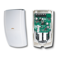
1.Unwind the screw on the side of the detector until loose; the screw will be
retained in the product (see Figure 1, item 1).
2.Lift detector lid out from the base and off the lugs at the opposite end to the
screw (see Figure 1, item 2).
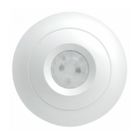
3.Fix the base to the ceiling between 2.4 m and 3.6 m (8 and 12 ft) from the floor.
For flat mounting use a minimum of 2 screws (DIN 7998) in any of the available
positions (see Figure 2). Rear tamper pull-out needs to be secured to the mounting
surface to meet Grade 3 requirements.
4.Wire the detector (see Figures 3 and Figure 7). 5.Select the desired option
settings (see Figure 3 -Part 6 ).
On either power-up or reapplication of the front cover the detector will
temporarily enter an auto-optimisation mode to adapt to it’s
environment. This will be shown by the LED’s flashing in sequence.
Allow 3 minutes for the optimisation to complete.
• During optimisation ensure that there are no obstructions in close proximity (<1m) to the
detector that will not be present during normal operation, as this could trigger a false masking
signal.
 Loading...