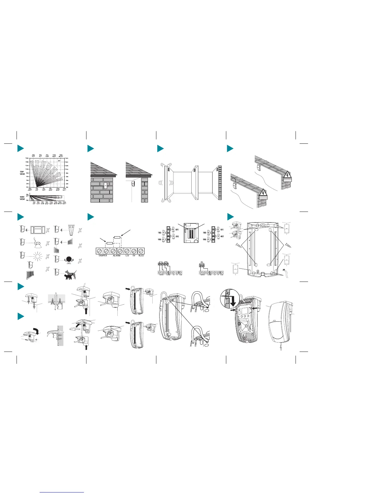
15 DETECTOR KNOCKOUTS
17 WALL MOUNT BRACKET
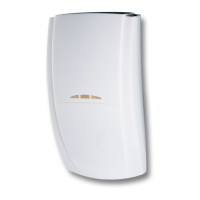
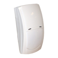
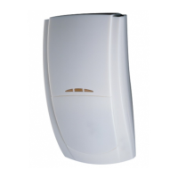
10 MOUNTING THE PRESTIGE IR
For indoor use only
9 COVERAGE PATTERN
Volumetric
2
2 41 3
1 3 4
5
7
5
8
✗
Seal all holes
INS 252-4
See Mounting Height Diagram (Section 7)
6
✓
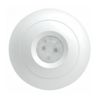
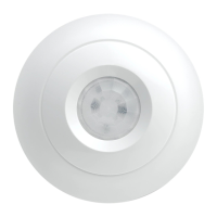
16 CEILING MOUNT BRACKET
13 CHOOSING A LOCATION
Avoid common false alarm sources
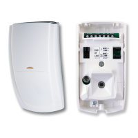
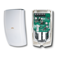
12 WIRING
Do not run cable parallel to mains wiring
✓
✗
14 EOL RESISTOR JUMPER LINKS
The jumper links JP3 and JP4 (see Section 4) are used to select resistances for
End-of-Line (EOL) wiring applications.
If EOL wiring is not used, the headers should be left in the default (O/C) position.
If the required resistance values are not available, leave the headers in the O/C position
and wire in external resistors as normal.
EOL Settings for Texecom Panels JP3 JP4
Premier & Premier International 2k2 4k7Cexample
EXAMPLES OF EOL JUMPER LINK USE
Double Pole
(jumper links not used)
Dual End-of-Line
(DEOL)
JP3 Selects the End-of-Line
resistance. Equivalent to wiring
a resistor of the selected value
as shown.
JP4 Selects the resistance
across the alarm relay.
Equivalent to wiring a resistor
of the selected value as shown.
TAMPER - JP3 ALARM - JP4
11 MOUNTING THE PRESTIGE IR
Mount on a stable surface
✓
✗
✓
✗
✓