Do you have a question about the Textron Greenlee 854DX and is the answer not in the manual?
Explains safety symbols and general hazard warnings for safe operation.
Covers safe practices for tool operation, extension cords, and pinch points.
Details safety for tool maintenance, work area, and environmental considerations.
Steps for removing and disassembling the roller assembly.
Procedures for removing and disassembling the roller support assembly.
Instructions for servicing the eccentric roller shaft.
Maintenance for outer control box and roller stop plate.
Steps for servicing the front drive chain and inner control box.
Guidance on assembling the front sprocket and encoder.
Instructions for removing and servicing the motor and gearbox.
Procedures for countershaft and wheeled base maintenance.
Steps for servicing the control board unit and pendant switch.
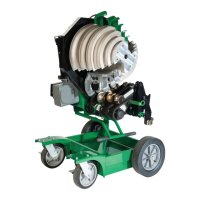
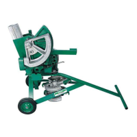
Exploded view of the main bender components.
Diagrams of the bender base and control box assemblies.
Visual representation of various sub-assemblies and parts.
Lists parts for base, guards, and sprockets.
Parts for control box, screw kits, and various assembly kits.
Lists encoder, idler, and handle kits.
Parts related to roller assemblies and lift handle.
Parts for cam, lever, and hardware kits.
Parts for release kits, guards, and other individual items.
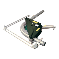
Details shoe groups for EMT, IMC, and rigid conduit.
Details shoe groups for PVC-coated rigid conduit.
| Brand | Textron |
|---|---|
| Model | Greenlee 854DX |
| Category | Construction Equipment |
| Language | English |