TEXTRON
LYCOMING
OPERATOR'S MANUAL
SECTION
1
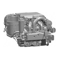
10-540 & 10-540 SERIES
Crankshaft
- The crankshaft is made from
a chrome nickel molybdenum
steel forging. All
bearing journal
surfaces are
nitrided. Freedom
from tor-
sional
vibration
is assured by
a system of
pendulum type
dynamic
counterweights.
Connecting Rods
- The connecting
rods are made
in the form
of "H" sec-
tions
from alloy
steel forgings. They
have replaceable
bearing
inserts in
the crankshaft
ends and bronze
bushings
in the piston ends.
The bearing
caps on the crankshaft ends
are retained by two bolts and
nuts through
each cap.
Pistons - The
pistons are
machined from
an aluminum alloy
forging. The
piston pin is a full floating type
with a plug located in each
end of the pin.
Depending on
the cylinder assembly,
pistons
may be machined
for either
three
or four rings and may employ
either half-wedge or full-wedge
rings.
Consult the
latest revision
of Service Instruction
No. 1037
for proper piston
and ring combinations.
Accessory
Housing
- The accessory
housing is
made from an
aluminum
casting and
is fastened to
the rear of the
crankcase and
the top rear of
the sump.
It forms a
housing for the
oil pump and
the various accessory
drives.
Oil Sump (0-540, IO-540-C,
-D, -J, -N, -R) - The sump
incorporates an
oil drain
plug, oil suction
screen, mounting
pad for carburetor
or fuel
injec-
tor, the intake
riser and intake
pipe connections.
Oil Sump and Induction
Assembly (Except 0-540, 10-540-C,
-D, -J, -N,
-R) - This assembly consists
of the oil sump bolted to a mated
cover con-
taining intake pipe
extensions for the induction
system. When bolted
together
they form
a mounting pad
for the air inlet
housing. Fuel
drain plugs
are provided
in the
cover and
the sump
incorporates
oil
drain plugs
and
an oil suction screen.
Cooling
System -
These engines
are designed to
be cooled by air
pressure
actuated by
the forward speed
of the aircraft.
Baffles are
provided to build
up a pressure
and force the air
through the
cylinder fins. The
air is then
exhausted
to the
atmosphere through
gills or
augmentor tubes
usually
located at
the rear of the
cowling.
 Loading...