LYCOMING OPERATOR’S MANUAL SECTION 1
O-320 SERIES DESCRIPTION
SECTION 1
DESCRIPTION
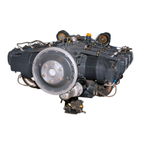
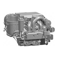
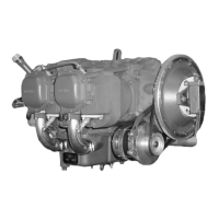
The O-320 series are four cylinder, direct drive and, horizontally opposed, air cooled engines.
In referring to the location of the various engine components, the parts are described in their relationship
to the engine as installed in the airframe. Thus, the power take-off end is considered the front and the
accessory drive end the rear. The sump section is considered the bottom and the opposite side of the engine
where the shroud tubes are located the top. Reference to the left and right side is made with the observer
facing the rear of the engine. The cylinders are numbered from front to rear, odd numbers on the right, even
numbers on the left. The direction of rotation for accessory drives is determined with the observer facing the
drive pad. The direction of rotation of the crankshaft, viewed from the rear, is clockwise.
Cylinders – The cylinders are of conventional air cooled construction with the two major parts, head and
barrel, screwed and shrunk together. The heads are made from an aluminum alloy casting with a fully
machined combustion chamber. Rocker shaft bearing supports are cast integral with the head along with
housings to form the rocker boxes for both valve rockers. The cylinder barrels, which are machined from
chrome nickel molybdenum steel forgings, have deep integral cooling fins and the inside of the barrels are
ground and honed to a specified finish.
Valve Operating Mechanism – A conventional type camshaft is located above and parallel to the crankshaft.
The camshaft actuates hydraulic tappets which operate the valves through push rods and valve rockers. The
valve rockers are supported on full floating steel shafts. The valve springs bear against hardened steel seats
and are retained on the valve stems by means of split keys.
Crankcase – The crankcase assembly consists of two reinforced aluminum alloy castings, fastened together
by means of studs, bolts and nuts. The mating surfaces of the two castings are joined without the use of a
gasket, and the main bearing bores are machined for use of precision type main bearing inserts.
Crankshaft – The crankshaft is made from a chrome nickel molybdenum steel forging. All bearing journal
surfaces are nitrided.
Connecting Rods – The connecting rods are made in the form of “H” sections from alloy steel forgings.
They have replaceable bearing inserts in the crankshaft ends and bronze bushings in the piston ends. The
bearing caps on the crankshaft ends are retained by two bolts and nuts through each cap.
Pistons – The pistons are machined from an aluminum alloy. The piston pin is of a full floating type with a
plug located in each end of the pin. Depending on the cylinder assembly, pistons may employ either half
wedge or full wedge rings. Consult the latest revision of Service Instruction No. 1037 for proper piston and
ring combinations.
Accessory Housing – The accessory housing is made from an aluminum casting and is fastened to the rear of
the crankcase and the top rear of the sump. It forms a housing for the oil pump and the various accessory
drives.
Oil Sump – The sump incorporates an oil drain plug, oil suction screen, mounting pad for carburetor, the
intake riser and intake pipe connections.
1-1
 Loading...