SECTION 1 LYCOMING OPERATOR’S MANUAL
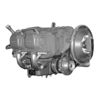
DESCRIPTION O-320 SERIES
Cooling System – These engines are designed to be cooled by air pressure. Baffles are provided to build up
a pressure and force the air through the cylinder fins. The air is then exhausted to the atmosphere through
gills or augmentor tubes usually located at the rear of the cowling.
Induction System - Lycoming O-320 series engines are equipped with a float type carburetor. Particularly
good distribution of the fuel-air mixture to each cylinder is obtained through the center zone induction
system, which is integral with the oil sump and is submerged in oil, insuring a more uniform vaporization of
fuel and aiding in cooling the oil in the sump. From the riser the fuel-air mixture is distributed to each
cylinder by individual intake pipes.
A brief description of the carburetors follows:
The Precision Airmotive MA-4SPA and HA-6 carburetors are of the single barrel float type equipped with
a manual mixture control and an idle-cut-off.
Lubrication System – The lubrication system is of the pressure wet sump type. The main bearings,
connecting rod bearings, camshaft bearings, valve tappets, push rods and crankshaft idler gears are
lubricated by means of oil collectors and spray. The oil pump, which is located in the accessory housing,
draws oil through a drilled passage leading from the oil suction screen located in the sump. The oil from the
pump then enters a drilled passage in the accessory housing, where a flexible line leads the oil to the
external oil cooler. In the event that cold oil or an obstruction should restrict the flow of oil to the cooler, an
oil cooler bypass valve is provided. Pressure oil from the cooler returns to a second threaded connection on
the accessory housing from which point a drilled passage conducts the oil to the oil pressure screen, which
is contained in a cast chamber located on the accessory housing below the tachometer drive.
The oil pressure screen is provided to filter from the oil any solid particles that may have passed through
the suction screen in the sump. After being filtered in the pressure screen chamber, the oil is fed through a
drilled passage to the oil relief valve, located in the upper right side of the crankcase in front of the
accessory housing.
This relief valve regulates the engine oil pressure by allowing excessive oil to return to the sump, while
the balance of the pressure oil is fed to the main oil gallery in the right half of the crankcase. During its
travel through this main gallery, the oil is distributed by means of separate drilled passages to the main
bearings of the crankshaft. Separate passages from the rear main bearing supply pressure oil to both
crankshaft idler gears. Angular holes are drilled through the main bearings to the rod journals. Oil from the
main oil gallery also flows to the cam and valve gear passages, and is then conducted through branch
passages to the hydraulic tappets and camshaft bearings. Oil enters the tappets through indexing holes and
travels out through the hollow push rods to the valve mechanism, lubricating the valve rocker bearings and
valve stems. Residual oil from the bearings, accessory drives and the rocker boxes is returned by gravity to
the sump, where after passing through a screen it is again circulated through the engine. Pressure build-up
within the crankcase is held to a minimum by means of a breather located on the accessory housing.
Priming System – Provision for a primer system is provided on all engines.
Ignition System – Dual ignition is furnished by two magnetos. Consult Table 1 for model application.
Bendix magnetos are designed to permit periodic internal maintenance; Slick Electro magnetos are designed
to operate for approximately 900 hours without internal maintenance.
1-2

 Loading...