2. ASSEMBLY (WHERE NECESSARY)
emove all the items from the carton and strip the protective packaging materials off each item. Returns are only
o the forks using the
eat with the four allen headed bolts, making sure the adjustment levers are to the
ont.
seat
and out. Replacing the seat is just a reversal of
p or down to
ated at the top rear of the
ver. rectly.
Batteri safety in transit the main supply leads may have been disconnected from the batteries. The black
the other. These will be taped to the
bolts are correctly
3. PRE E THE BREEZE FOR FIRST USE
will requ
safe are
obstacle lat. Mark a practice course for straight line driving, turning in confined spaces, reversing
nd driving around obstacles.
l Levers - The speed of Breeze is controlled by the
ver located on the right hand handlebar and shown in Fig 1.1.
parking brake will engage and stay on until the machine
oves off again. The lever is also fitted with a panic sensor which is
ctivated if the lever is pulled in hard against the handlebar. If this
appens all power to the motor will be shutdown and the brakes will
me on immediately causing the machine to stop very suddenly.
The Breeze was pre-delivery inspected and tested prior to dispatch. The batteries may have been disconnected for
delivery purposes only.
R
accepted when the product is shipped in the original cartons with the original packing material installed.
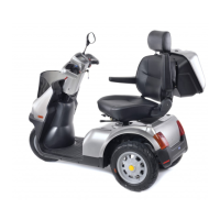
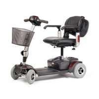
Breeze 3 will have had the front wheel and the seat removed. Replace the front wheel int
components supplied and refit the front brake cable. Ensure the wheel nuts are securely tightened. Next fit the
seat plate to the base of the s
fr
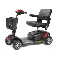
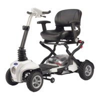
Breeze 4 will just have the seat back and tiller folded down.
Removal and Replacement of seat – To remove seat, release the seat locking lever, fig 5.1, and turn
through 180° so that it faces to the rear. Now lift seat straight up
the above.
Tiller Adjustment – Release the tiller adjusting lever by pulling outwards, then move the tiller u
your choice. Make sure it locks in before use, fig 5.3.
Rear Cover Removal – Remove seat, then unscrew the two black fixing screws loc
co Remove cover. Replacement is just a reversal of the above, ensuring the cover locates cor
es – For
lead would have been disconnected from one battery and the red lead from
batteries in an obvious position as will the fixing bolts. Simply reconnect the leads ensuring the
tightened.
PAR
If you receive your Breeze packaged and it has to be assembled see the section covering Assembly. The batteries
ire charging - refer to Charging the Breeze for details.
Care! Warning
The Breeze is easy to drive but it is essential that you familiarise yourself with the controls and learn to drive it in a
a with sufficient room to manoeuver for your safety and that of others. The area should be free of
s and reasonably f
a
4. THE CONTROLS AND INSTRUMENT PANEL
Figs 1-4 Provide details of the control system. Listed below are the various controls and their uses.
1. Speed Contro
le
1.4
1.1
1.2
1.3
Fig 1
Always use the lever gently, remembering that the more you squeeze
the lever in the quicker you will go. To stop simply release the lever,
the braking is completely automatic and when the machine has
stopped the
m
a
h
co
3