EasyManua.ls Logo

The Andersons 2000 SR - User Manual

The Andersons 2000 SR
8 pages
Print Icon
To Next Page IconTo Next Page
Loading...
To assemble your new spreader,
we highly recommend that you
read all the instructions
thoroughly, familiarize yourself
with the assembly and
components, and verify that all
parts are included in the
package.
The following tools:
1/2”, 7/16” and 3/8” open-end wrenches
(or adjustable wrench)
Pliers
—Phillips head screwdriver
Grease gun
Assembly, Use and Care
You have purchased the highest quality professional broadcast spreader available on the market today. The
Model 2000 SR is the accumulation of proven performance and will provide you with years of trouble-free service.
In the event you should have any questions or comments, please call our professional support staff.
Thank You!
Our toll-free number is 1-800-225-2639 (U.S. Only)
Before You Begin ...
You Will Need ...
Model 2000 SR
Professional Rotary Spreader
Question and Answer IconNeed help?

Do you have a question about the The Andersons 2000 SR and is the answer not in the manual?

Summary

Assembly, Use and Care

Thank You!

Expresses gratitude for purchasing the broadcast spreader and offers support.

Before You Begin

Recommends reading instructions, familiarizing with components, and verifying parts.

You Will Need

Lists the necessary tools for assembly, including wrenches, pliers, screwdriver, and grease gun.

Assembly

Step 1: Wheel Attachment

Attaching the drive and idler wheels to the axle using cotter pins.

Step 2: Frame Attachment

Securing the frame to the spreader body using Phillips screws and locknuts.

Step 3: Upper Handle Attachment

Connecting the upper handle to the frame with carriage bolts and locknuts.

Step 4: Shutoff Rod Connection

Inserting the main shutoff connecting rod into the lever and securing with a cotter pin.

Step 5: Shutoff Rod Nut Adjustment

Threading nuts onto the main shutoff control rod and pivot lever arm for adjustment.

Step 6: Shutoff Plate Alignment

Adjusting nuts to ensure the main shutoff plate ports close completely.

Assembly Continued

Step 7: Auxiliary Shutoff Bracket

Attaching auxiliary shutoff bracket and securing the push-pull control cable.

Step 8: Lever Bracket Attachment

Attaching the lever bracket to the handle and connecting the deflector rod.

Step 9: Deflector Rod Connection

Connecting the deflector control rod to the deflector shield assembly.

Step 10: Lubrication

Lubricating grease fittings on axle bearings and gear carrier, and gears.

Maintenance

Post-Use Care

Emptying and sealing the spreader after each use to prevent moisture clumping.

Cleaning and Drying

Thoroughly washing the spreader and drying it to prevent corrosion.

Periodic Greasing

Greasing axle bearing housings and oiling the impeller shaft bearing.

Pivot Point Lubrication

Oiling pivot points on control linkage and the deflector.

Gear Inspection and Lubrication

Cleaning and lubricating gears by removing gearbox covers.

Gear Mesh Check

Checking and adjusting axle gear and pinion gear mesh for smooth operation.

Tire Pressure

Maintaining tire pressure at a maximum of 20 psi.

Axle Reassembly

Ensuring correct reassembly for drive wheel and rotor plate rotation.

Operation

How to Use

Guidance on setting up and using the spreader for application.

Rate and Cone Settings

Setting the rate control and cone settings based on product bag recommendations.

Filling the Hopper

Closing the main shutoff lever before filling the hopper.

Starting and Stopping

Opening shutoff lever to start spreading and closing before stopping.

Spreader Level

Maintaining a level hopper position for even spreading.

Swath Width and Speed

Using recommended swath width and walking speed for application.

Test Application

Testing rate and pattern on a small area before large application.

Deflector Shield Use

Using the deflector shield to block off the right swath portion.

Hopper Cover Use

Using the hopper cover to protect turf products during transportation.

Calibration Instructions

Initial Setup

Closing shutoff lever, setting rate control plate to 'E', and opening shutoff lever.

Calibration Key Insertion

Inserting the Calibration Key vertically into the center port hole.

Fit Check

Checking if the spreader is properly calibrated by the fit of the calibration key.

Adjustment Procedure

Loosening knob, sliding plate left, inserting key, and holding with shutoff lever.

Rate Control Rod Contact

Sliding the rate control plate to contact the rate control rod.

Tightening and Removal

Tightening the rate control knob and removing the calibration key.

Pointer Adjustment

Loosening nuts, sliding pointer to center on 'E', and re-tightening screws.

Ordering Parts

Parts Identification

Guidance on using the diagram for identifying specific parts for ordering.

Ordering Information

Details on how to order parts, including required information.

Contact Information

Providing a toll-free number and website for more information and orders.

Warranty

Warranty Coverage

Details the one-year warranty for defects and lifetime warranty for specific parts.

Warranty Exclusions

Lists conditions that void the warranty, such as misuse or unauthorized modification.

Limitation of Liability

States The Andersons' sole obligation and limits liability for incidental damages.

Contact for Warranty

Provides contact information for warranty questions and feedback.

Overview

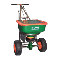
The Andersons Model 2000 SR is a professional rotary spreader designed for broadcast application of turf products. It is engineered for durability and precision, offering years of trouble-free service for both professional and commercial users.

Function Description

The Model 2000 SR's primary function is to accurately and evenly spread granular materials, such as fertilizers, seeds, and other turf products, over a designated area. It utilizes a rotary mechanism to broadcast the material, ensuring a wide and consistent spread pattern. Key features include a main shutoff lever for precise control over material flow, an auxiliary shutoff for edge control, and a deflector shield to block off portions of the swath width, preventing over-application in specific areas. The spreader also incorporates a rate control plate and a helical cone for adjusting the application rate and spread pattern, respectively.

Important Technical Specifications

While specific numerical specifications like hopper capacity or spread width are not explicitly detailed, the manual highlights several design elements that contribute to its technical performance:

  • Durable Construction: The spreader is built with high-quality components, including an axle gear, gear support, pinion gear, axle, and axle bearings, all covered by a limited lifetime warranty for defects in materials and workmanship (for non-commercial use).
  • Adjustable Flow Control: The rate control plate allows for precise adjustment of the material flow rate, indicated by letter settings. The helical cone, with numerical settings, controls the left and right spread pattern.
  • Wheel System: It features drive and idler wheels, secured with cotter pins, designed for smooth operation. The wheels are identical and interchangeable.
  • Grease Fittings: Multiple grease fittings are strategically placed on the axle bearing housings and gear carrier to facilitate regular lubrication and extend component lifespan.
  • Tire Pressure: Maximum tire pressure is specified at 20 psi, emphasizing the importance of proper inflation for optimal performance.
  • Material Compatibility: Designed for granular turf products, ensuring even distribution.

Usage Features

The Model 2000 SR is designed for user-friendly operation with several features aimed at enhancing control and application accuracy:

  • Assembly: The manual provides detailed, step-by-step instructions for assembly, including attaching wheels, handles, shutoff mechanisms, and the deflector shield. It recommends applying oil to bolt threads to ease locknut assembly.
  • Calibration: The spreader is factory-calibrated, but instructions are provided for occasional calibration checks and adjustments using a calibration key. This ensures consistent and accurate application rates over time.
  • Rate and Pattern Control: Users can adjust the application rate by sliding the rate control plate to align with a desired letter setting. The spread pattern (left and right) is controlled by rotating the index tab on the orange helical cone to a specific number.
  • Main Shutoff Lever: This lever controls the primary flow of material from the hopper. It should be pulled to the closed position before filling the hopper and opened only when the spreader is moving forward.
  • Auxiliary Shutoff and Deflector Shield: These features work in conjunction to control the spread pattern, particularly for edge application. The deflector shield, when in the "ON" (down) position, blocks off the right side of the swath. The auxiliary shutoff, when pushed forward to the "CLOSED" position, prevents excessive application at the center of the swath when the deflector is in use. Users are reminded to re-open the auxiliary shutoff (pull knob back) when returning to a full swath width.
  • Hopper Cover: A hopper cover is included to protect turf products from light rain or windy conditions during transportation, preserving material quality.
  • Operating Speed: The recommended operating speed is 3 MPH (a brisk walking pace), and material should only be applied while pushing the spreader forward, not pulling it.
  • Level Operation: Maintaining a level handle during operation is crucial to prevent uneven spreading.
  • Test Application: Users are advised to test the rate and pattern on a small area before treating a larger area, as actual application rates can vary based on weather, spreader condition, and walking speed.

Maintenance Features

Regular maintenance is emphasized to ensure the longevity and optimal performance of the Model 2000 SR:

  • Cleaning: After each use, the spreader should be emptied, and any unused material returned to its original container. The spreader, including the impeller shaft bearing, should be thoroughly washed and dried to prevent corrosion. All residue must be cleaned from the rotor plate.
  • Lubrication: Periodic greasing of the axle bearing housings and gear carrier is required, as indicated in the assembly steps. A small amount of grease should also be applied to the gear teeth after cleaning. A few drops of oil should be applied to the impeller shaft bearing and allowed to penetrate. Pivot points on all control linkage, the deflector, and the spring inside the rate control housing also require oiling.
  • Gear Inspection: Gear mesh should be checked regularly, especially during high-use periods. Minimal clearance between the axle gear and pinion gear is desired, but it should not be tight. Adjustment involves loosening the axle collar set screw, holding the gears together, sliding the axle collar against the gear carrier, and re-tightening the set screw.
  • Tire Pressure: Maintaining tire pressure at a maximum of 20 psi is important. Overfilling should be avoided.
  • Axle Disassembly/Reassembly: If the axle needs to be disassembled, it must be reassembled correctly, ensuring the drive wheel is on the right-hand side to prevent an incorrect spread pattern and ensure the rotor plate rotates counter-clockwise.
  • Gearbox Cover: The gearbox cover halves should be periodically removed to clean and inspect the gears, and then reinstalled with retainer clips.

The Andersons 2000 SR Specifications

General IconGeneral
BrandThe Andersons
Model2000 SR
CategorySpreader
LanguageEnglish