Do you have a question about the Thermal Zone MSC424HP13230A and is the answer not in the manual?
| Brand | Thermal Zone |
|---|---|
| Model | MSC424HP13230A |
| Category | Air Conditioner |
| Language | English |
Important note for qualified HVAC contractors regarding installation and maintenance procedures.
Essential safety precautions and guidelines for operating the unit safely and correctly.
Lists items necessary for unit installation that may need to be purchased separately.
Discusses application-specific requirements and considerations for different environments.
Guidance on locating and mounting the indoor unit, considering airflow and obstacles.
Details line set lengths, diameters, and catalog numbers for model compatibility.
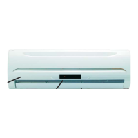
Describes the wireless remote controller and microprocessor controller for unit operation.
Information on optional Low Ambient Controller and Condensate Pump.
Instructions for unboxing the indoor and outdoor units and storing the remote.
Guidance on selecting the installation location for the indoor unit, considering clearance.
Details on drilling wall penetrations for line sets, wiring, and condensate drainage.
Instructions for securely mounting the indoor unit bracket to the wall, ensuring it's level.
Guidance on preparing and feeding line sets, condensate hose, and wiring through the wall opening.
Steps for attaching the indoor unit to the mounting bracket and ensuring it's plumb and level.
Specifies required clearances for the outdoor unit and placement considerations.
Instructions for connecting and routing refrigerant line sets, avoiding kinks and specific fittings.
Procedure for evacuating the system to remove moisture and ensure proper vacuum levels.
Guidelines for electrical wiring, breaker sizing, and connecting power to the unit.
Instructions for wiring controls between indoor and outdoor units, emphasizing correct connections.
Details on connecting the condensate hose to ensure proper drainage according to local codes.
Procedure for releasing refrigerant charge, opening valves, and powering the system for initial start-up.
Information on refrigerant charge for various line set lengths and operating conditions.
Detailed technical specifications for MSC424HP13230A and MSC424A13230A models.
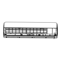
Specific details regarding indoor unit components like fan motor, coils, and dimensions.
Specific details regarding outdoor unit components like compressor, fan, and dimensions.
Continuation of outdoor unit specifications, including refrigerant charge and pipe dimensions.
Data on pipe diameters, maximum distances, and installation kit catalog numbers.
Illustrates low pressure readings vs. outdoor temperature during cooling operation.
Illustrates low pressure readings vs. outdoor temperature during heating operation.
Outlines the product warranty terms, coverage, exclusions, and activation process.
Provides essential contact information and hours for technical assistance.