5-4 Integrated Remote Monitor Unit Electrical Maintenance
CSR-20 & CSR-40, September 1999
easy to locate because no other devices are connected between
the MMU and CCU. The MMU attempts to communicate with
the CCU every 10 seconds until it receives a response.
The ideal place to begin diagnostics is at the CCU’s
receive data (RXD) input. Use an oscilloscope to determine if
the signal is traveling to the CCU. If the communications
between the MMU and CCU is unsuccessful, then the problem
exists in either the cable or the serial card.
Disconnect the CCU from the cable nest on the side of the
MMU enclosure. Using the oscilloscope probe, check the seri-
al transmit data (TXD) pin #3 of the CCU connector located in
the cable nest to determine if the signal is reaching the connec-
tion. If the signal is present, the problem is in the cable
between the MMU and the CCU.
If the signal is not present, the problem exists in either the
cable between the card cage and the cable nest, or the serial
card itself. Proceed to Problem 2.
If the container does not respond to an operator initiated
request (message “CONTAINER NO. NOT FOUND IN NET”
or “NO RESPONSE FROM CONTAINER NO.” appears on
the MMU upper screen), check Container No. to ensure it is
correct. Check for the letter O instead of zero (0), the letter I
instead of one (1), etc. If the container number is correct, pro-
ceed to Problem 3.
Also, refer to the Communications Troubleshooting chap-
ter in the MMU Manual.
Problem 1: MMU Does Not Communicate with the
Network
• Symptom: Message “COMMUNICATIONS RECOV-
ERY BEGUN” appears in the Alarm Field of the MMU.
• System Operation: The MMU sends a message to the
CCU every 10 seconds, to which the CCU should
respond. When the MMU receives the response from the
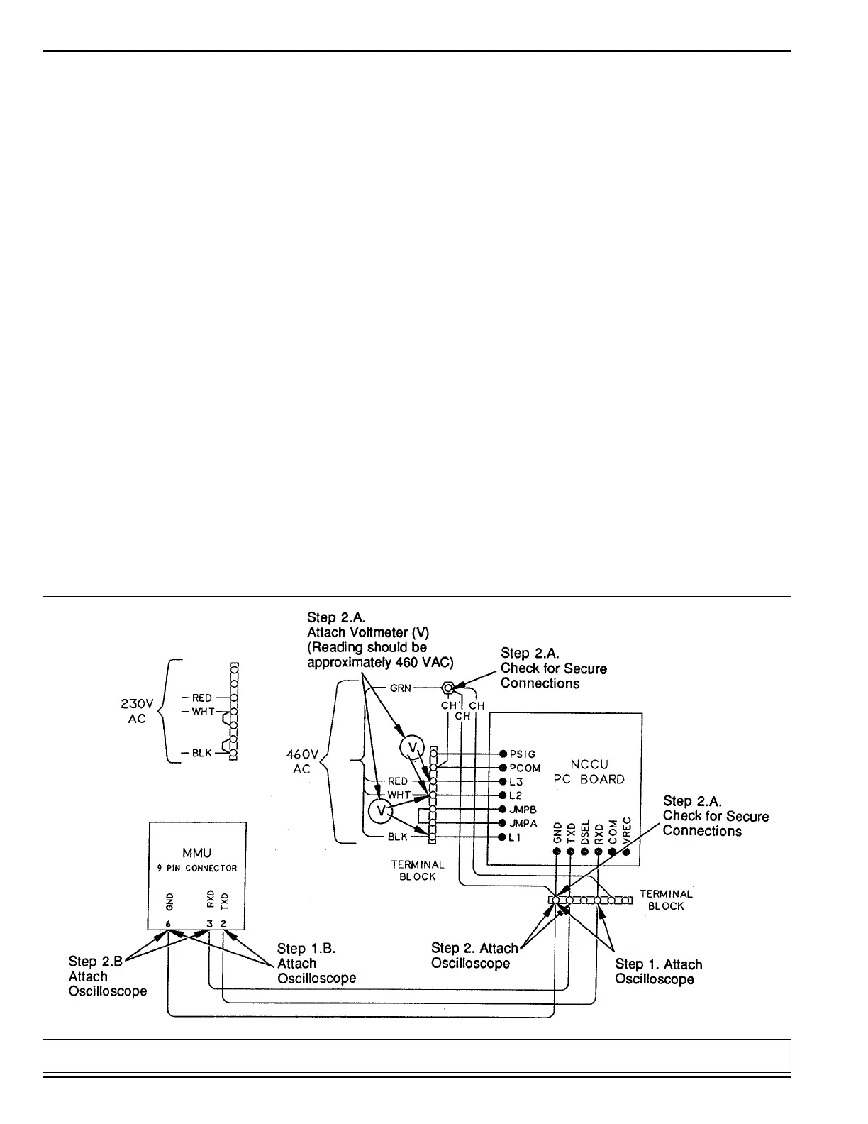
CCU, it clears the alarm message. See the RMU MMU
Section diagram. Attach an oscilloscope as shown on the
diagram for the following steps.
Problem 1 Diagnosis:
1. Check RXD pin at CCU end of the MMU-CCU serial
cable, see Step 1 callout on diagram.
a. If RXD signal is present every 10 seconds, go to Step
2.
b. If RXD signal is not present, check for signal at
MMU end of cable; see Step l.B. callout on diagram.
• If signal is present, check cable for continuity,
repair or replace.
• If signal is not present, check MMU internal
cable and serial card in MMU, repair or replace
as necessary.
Problem 1: RMU/MMU Section Diagram
 Loading...