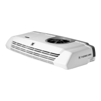
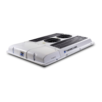
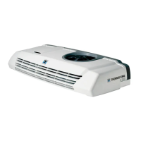
Do you have a question about the Thermo King V-400 and is the answer not in the manual?
General safety guidelines for unit operation and maintenance.
Information on refrigerant handling, environmental concerns, and first aid.
Handling precautions and first aid for refrigeration oil contact.
Safety precautions for electrical systems, including microprocessor service and welding.
Detailed warnings and procedures for handling high and low voltage electrical hazards.
Visual examples of important safety decals found on the unit.
Specific notes and procedures for working with DSR microprocessor units.
Visual representation of the DSR microprocessor system components and connections.
Overview of the DSR units, their function, and main assemblies (In-Cab Control Box, ECM).
Detailed description of key components like microprocessors, PCBs, fuses, and relays.
Explanation of how the unit receives electrical power from vehicle battery or standby sources.
Description of external components like sensors, switches, valves, motors, and their functions.
List of specific unit models and their associated evaporators/condensers covered by the manual.
How the microprocessor software controls unit operations based on inputs and setpoints.
Information on checking software revision and parameters in the Installation Menu.
Description of automatic unit operation modes like Cool, Null, and Heat.
Overview of the four main menu groups (Main, Hourmeters, Information, Installation) in the In-cab Control Box.
Visual guides illustrating the navigation and screens within the DSR µP Controller menus.
Details on features configurable via the Main, Hourmeters, Information, and Installation menus.
Description of the In-cab Control Box, including keypad and display functions.
Explanation of the Standard Display, including icons and how readings are shown.
Details on what the Standard Display shows during normal operation and system checks.
Procedure for restarting the unit after an alarm condition has been corrected.
How the unit automatically restarts after an alarm condition is resolved.
Explanation of when the unit's audible warning buzzers are activated.
Step-by-step instructions for adjusting the temperature setpoint via the In-cab Control Box.
Procedure for manually starting a defrost cycle using the In-cab Control Box.
How to view the installed software revision number through the Information Menu.
Instructions on how to view, identify, and clear alarm codes from the In-cab Control Box.
Important notes and precautions for working with DSR µP Controller microprocessors.
Procedures to prevent damage to microprocessors and circuit boards from ESD.
General tips and best practices for diagnosing DSR µP Controller issues.
Troubleshooting steps for addressing specific alarm codes displayed by the DSR µP Controller.
Troubleshooting guidance for unit issues that do not trigger specific alarm codes.
Key considerations for effective troubleshooting, including system vs. control issues.
Procedures related to microprocessor setup, ESD, welding, and hourmeter settings.
Procedure for the removal and replacement of printed circuit boards (PCBs).
Other service procedures, including sensor tests and connector repairs.
Information on DSR µP controller software versions and their compatibility.
List of available schematic diagrams for various DSR µP Controller unit models.
List of available wiring diagrams for various DSR µP Controller unit models.
| Brand | Thermo King |
|---|---|
| Model | V-400 |
| Category | Automobile Accessories |
| Language | English |


