Model 700 Series -40C _______________________________________________________________________________
i
Read This Instruction Manual.
Failure to read, understand and follow the instructions in
this manual may result in damage to the unit, injury to operat-
ing personnel, and poor equipment performance.
CAUTION! All internal adjustments and maintenance must
be performed by qualified service personnel.
The material in this manual is for information purposes only. The
contents and the product it describes are subject to change with-
out notice. Thermo Fisher Scientific makes no representations or
warranties with respect to this manual. In no event shall Thermo
be held liable for any damages, direct or incidental, arising out of
or related to the use of this manual.
MANUAL NUMBER 7020722
7 23939 5/29/07 Added “Adjust LN2 tank pressure relief valve to 30 PSI max blow-off” ccs
-- 24100 5/16/07 Clarified battery switch to Standby mode, with symbol ccs
4 23859/FR-1940 1/3/07 Clarified BUS install (probe/solenoid harness) instructions ccs
3 23700/FR-1919 10/09/06 Updated safety temp specs (from 5° - 40°C to 5° - 43°C) ccs
2 23170 2/9/06 Remote alarm connector is customer installed aks
-- 22930 2/9/06 WEEE Directive aks
1 22895 8/16/05 Remove rotalock valve from compressor aks
0 -- 7/14/05 Release 3 aks
REV ECR/ECN DATE DESCRIPTION By
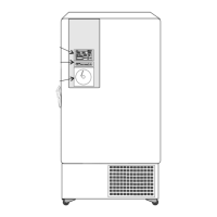
Model Capacity in Cubic Feet Voltage
722 13 120
727 13 230
728 17 120
729 17 230
Part
Number
Description Quantity
34040 Key Ring 1 (2 for double door units)
122005 Key 2 (4 for double door units)
380520 Neoprene Cap 2
510016 1/4-20 x 5-1/2” Bolt 2
402058 Vacu-Key 1
195763 Retaining Clip 1
370563 Remote Alarm Connector 1
Packing List
 Loading...