Do you have a question about the Thermor EVIDENCE 2 ELEC 1500 and is the answer not in the manual?
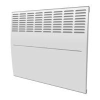
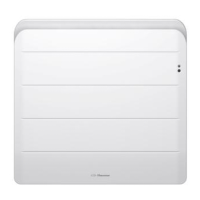
This document describes the Thermor EVIDENCE 2 ELEC 1500 convector heater, a Class II appliance designed for residential use and protected against splashed water (IP24). It is intended for installation in various rooms, including bathrooms (within Volume 2, provided controls are out of reach from a shower or bath). The device operates on a 220-240V 50Hz power supply.
The convector should be installed according to local regulations and trade practices, maintaining minimum clearance distances as shown in the diagrams. It should not be placed in draughts that could affect its control settings (e.g., under a fan or ventilation opening) or directly under a fixed mains power socket. For installations where the wall covering is foam, a spacer of the same thickness must be placed under the heater's support to ensure adequate air circulation behind the unit.
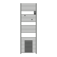
Vertical products should not be installed above an altitude of 1000 meters, as this can increase the air discharge temperature by approximately 10°C per 1000m of altitude. Horizontal installation of vertical products is prohibited.
The appliance is secured to a wall-mounted hook-on bracket. To install, first release the hook-on bracket by placing the radiant panel face down and using a flat-head screwdriver. The bracket is then fixed to the wall using drilling points A and B. It is crucial not to use the device with mobile feet or casters.
Electrical connection can be made via a 2-wire cable (Brown = Phase, Blue = Neutral) to a power socket or connection box (for mechanical thermostats), or a 3-wire cable (Brown = Phase, Blue = Neutral, Black = Pilot wire) to a connection box (for electronic thermostats with pilot wire). In humid areas, power sockets must be installed at least 25 cm above the floor. The installation must include an omnipole disconnection mechanism with a contact break distance of at least 3mm. Earthing of the convector is prohibited, and the black pilot wire must not be connected to earth. If the power cord is damaged, it must be replaced by a qualified electrician. If a pilot wire or piloted panel heater is protected by a 30mA differential, the pilot wire's power must also be protected by the same differential.
The control unit features a stop/0 switch, a temperature adjustment control knob, and a heating indicator light (V1).
Comfort Temperature Setting: This is the desired temperature when the room is occupied.
Eco Temperature Setting (Electronic Models Only): This is the desired temperature for unoccupied periods, recommended for absences longer than 2 hours.
Frost-Free Mode: This mode maintains a temperature of approximately 7°C, suitable for prolonged absences (over 24 hours).
Heating Indicator (V1 - Electronic Models): This light indicates when the heating element is active. It may flash when the temperature has stabilized.
Locking Controls: The control knob and switch can be locked or limited to prevent unauthorized manipulation (e.g., by children).
Pilot Wire Functionality: Products with a pilot wire can receive signals from a master unit for "Comfort," "Eco" (Comfort -3°C to -4°C), "Frost-Free" (approx. 7°C), and "Off" modes.
To maintain optimal performance, the upper and lower grilles should be cleaned with a vacuum cleaner or brush approximately twice a year. A professional check of the internal components is recommended every five years. Dirt accumulation on the grille due to polluted ambient air is not covered by warranty; in such cases, ensure proper room ventilation and clean air. The casing can be cleaned with a damp cloth; abrasive products should never be used.
The warranty is valid for 2 years from the date of original purchase, not exceeding 30 months from the date of manufacture. It covers the replacement of parts found to be defective in manufacturing. Labor, freight, and transport costs are not covered. The warranty does not cover damage due to neglect, shipping, accidents, incorrect installation, misuse, or failure to follow instructions. This document, along with the purchase invoice, must be presented for any warranty claims. The unit's type and serial number are located on the left side or behind the front grille.