Installation
11 12
Installation
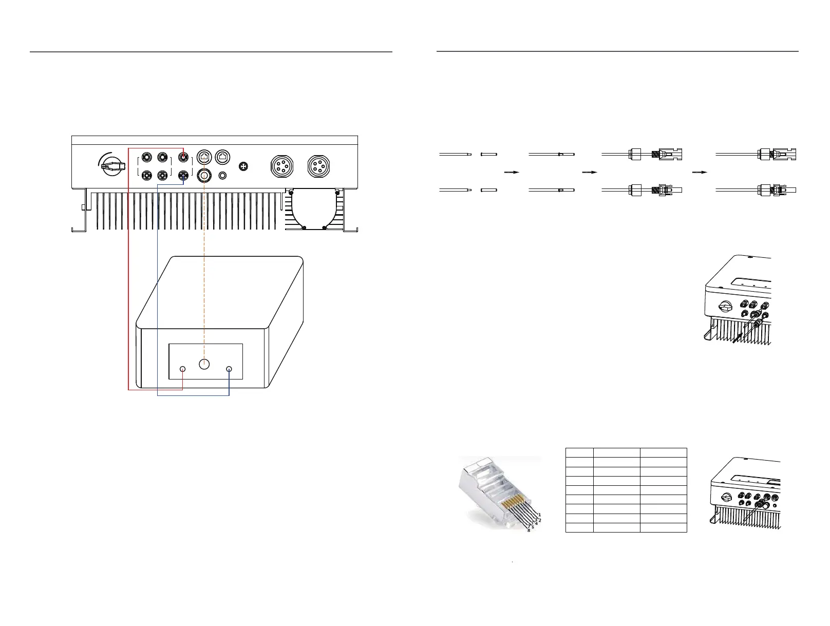
2.5 Battery Connection
Fig.2.1
Battery connection diagram
1
1) Use the right BAT connectors in the accessory box.
2) Choose 4 to 6 mm²(AWG 10) tin-plated cable to connect the battery and the inverter.
3) Make sure battery switch is off and battery nominal voltage meets EPH series
inverter’s specification before connecting battery to inverter.
STEP1:
Assemble the battery connectors from the accessory box.(battery cable must be firmly
crimped into connectors)
Fig.2.12
BMS
+
-
CAN
Batery Power
BMS
ON
OFF
PV1
+
-
PV2
Battery
+
-
+
-
Meter
DRED
WIFI
Power
Back-up On-Grid
STEP2:
Connect the battery connectors to the inverter.
There will be a click sound if connectors
are inserted correctly into battery plugs.
Fig.2.13
STEP3:
Connect the BMS cable between battery and inverter, insert the RJ45 connector with
water-proof cap into the port marked “BMS” on inverter and fasten the cap. Then insert the
other end of the cable into the battery port.
Position
Color
1
Orange&white
Orange
Green&white
Blue
Signel Name
485_A2
NC
Blue&white
Green
Brown&white
Brown
2
3
4
5
6
7
8
485_B2
CAN_H
CAN_L
NC
NC
NC
Fig.2.14