TA02982 E page 3 of 8
30
36
202
32
201
37
~ 8 ÷ 10 mm
(0.3 - 0.4 in.
)
90
91
− Set the tool in the release position by rotating the xed
handle (200). The moveable handle (203) will be released and
the main handle will rotate automatically to the operating
position .
− Operate moveable handle (203) for lower die advancement.
This rst stage rapidly closes the dies to the connector.
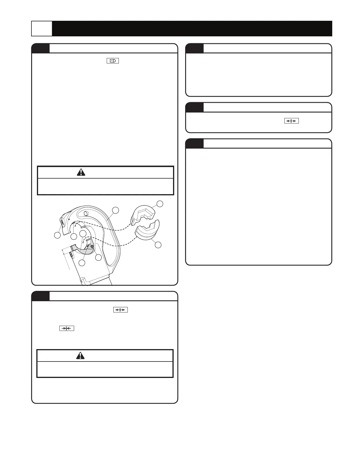
To replace dies proceed as follows: (Refer to Figure 2)
Upper die (91)
− Take the die off its guide by pushing the die/head release
pin (30).
− Insert replacement die until secured by the die/head retaining
pin (32).
Lower die (90)
− Take the die off its guide by pushing the die/head release
pin (36).
− Insert replacement die until secured by the die/ram retaining
pin (37). To facilitate this operation an advancement of the ram
by 8-10 mm (0.3 - 0.4 in.) is suggested.
− Continue operating the movable handle (203). The tool will
automatically change over to the high pressure stage. The ram
will advance until the dies meet.
− Continue pumping until the maximum pressure valve is
activated and a “click” is heard.
− Rotate the xed handle to release position
Close
handles. The ram will then retract, and the dies will open.
Make sure the dies are exactly positioned on desired crimp point,
otherwise re-open dies following instructions as per 2.4 and
reposition the connector.
DIE ADVANCEMENT
DIE REPLACEMENT
COMPRESSION
RELEASE OF DIES
WARNING
Never place the tool under pressure without inserting the
dies, this could cause damage to the head and the ram.
2.0 INSTRUCTION FOR USE
With the tool in the rest position prepare the tool as
follows: (see Figure 2)
− Select the appropriate die set for the connector.
− Insert the die (91) in the upper seat of the tool head until it is
locked by die/head pin (32). To ease the die insertion, keep
die/head release pin (30) depressed.
− Operate the tool (per 2.2) to advance the ram (202) 8-10 mm
(0.3 - 0.4 in.) and insert the die (90) into the seat on the ram
until it is locked by die/ram retaining pin (37). To ease this
operation, keep die/ram release pin (36) depressed.
− Insert the conductor in the connector.
− Position the connector between the dies and ensure the
correct location of the crimp.
− For ease of operation, the tool head can rotate through 180°.
PREPARATION
FIGURE 2
2.1
2.2
2.5
2.3
2.4
WARNING
DO NOT ATTEMPT TO TURN THE HEAD IF THE
HYDRAULIC CIRCUIT IS PRESSURISED.
 Loading...