MT8206
PRELIMINARY, SUBJECT TO CHANGE WITHOUT NOTICE MTK CONFIDENTIAL, NO DISCLOSURE
June, 2006
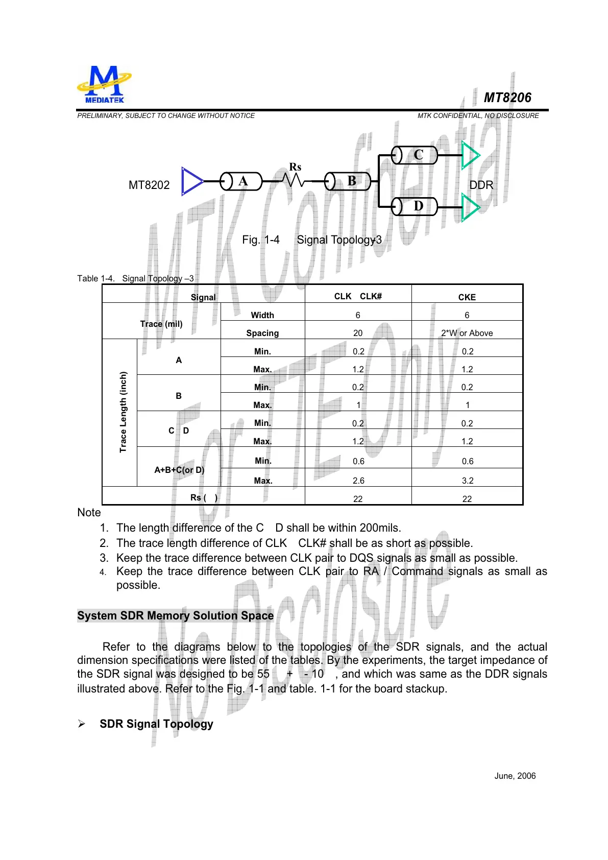
Rs
Fig. 1-4 Signal Topology -3
DDRMT8202
AB
C
D
Table 1-4. Signal Topology –3
Signal
CLK
CLK#
CKE
Width
6 6
Trace (mil)
Spacing
20 2*W or Above
Min.
0.2 0.2
A
Max.
1.2 1.2
Min.
0.2 0.2
B
Max.
1 1
Min.
0.2 0.2
C D
Max.
1.2 1.2
Min.
0.6 0.6
Trace Length (inch)
A+B+C(or D)
Max.
2.6 3.2
Rs ( )
22 22
Note
1. The length difference of the C D shall be within 200mils.
2. The trace length difference of CLK CLK# shall be as short as possible.
3. Keep the trace difference between CLK pair to DQS signals as small as possible.
4. Keep the trace difference between CLK pair to RA / Command signals as small as
possible.
System SDR Memory Solution Space
Refer to the diagrams below to the topologies of the SDR signals, and the actual
dimension specifications were listed of the tables. By the experiments, the target impedance of
the SDR signal was designed to be 55 + - 10 , and which was same as the DDR signals
illustrated above. Refer to the Fig. 1-1 and table. 1-1 for the board stackup.
¾ SDR Signal Topology