ELL14 Motorized SM1 Optic Rotator Chapter 5: Troubleshooting and FAQ
Rev. B, Feb 2020 Page 15
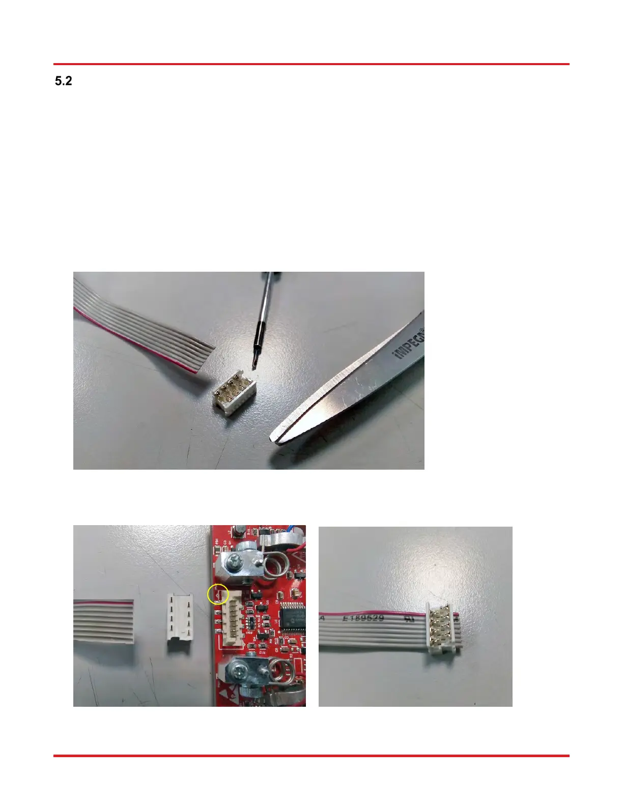
Notes on Making a Picoflex Cable for Use when Daisy Chaining Devices
The multi-drop communications bus offers the option of connecting the stage to a hybrid network of up to 16 Elliptec resonant
motor products and controlling the connected units with a device such as a microprocessor. When multiple units are connected
to the same interface board, all can be controlled simultaneously using either the software or the buttons on the interface board.
When making a cable to operate multiple devices it is important to observe the correct pin orientation. The following procedure
offers guidance in making such a cable.
1. Gather together the parts required.
a) Ribbon cable 3M 3365/08-100 (Farnell 2064465xxxxx).
b) Female crimped connectors as required - model number MOLEX 90327-0308 (Farnell order code 673160) (Qty 1
female connector above is shipped with each stage unit).
c) Suitable screwdriver and scissors or other cutting tool.
2. Orientate the first connector correctly to mate with the connector on the stage, then arrange the ribbon cable as shown
with the red wire aligned with pin 1 (identified on the pcb by a small triangle). Slide the connector onto the ribbon cable
as shown.
 Loading...