ELL14 Motorized SM1 Optic Rotator Chapter 5: Troubleshooting and FAQ
Page 16 DTN000522-D02
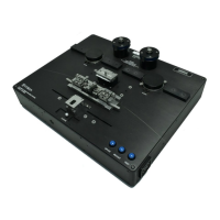
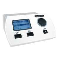
3. Using a screwdriver or other suitable tool, push down the crimp of each pin to make connection with the ribbon cable.
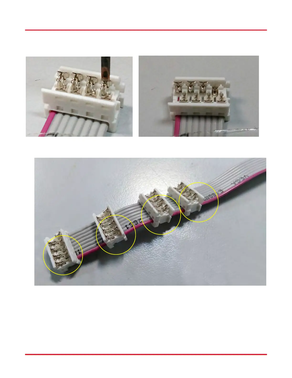
4. If other connectors are required they should be fitted at this point. Slide each connector onto the cable, paying attention
to the orientation as shown below, then crimp as detailed in step (3).
5. Fit the terminating connector which will mate with the interface board, taking care to align the cable red wire with pin 1
as detailed in step (2).
 Loading...