Page 16 20381-D02
Single- and Dual-Axis Scanning Galvo Systems for Large Beam Diameters
.
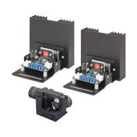
Fig. 3.11 J7 Command Input Connector Pin Identification
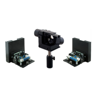
8) Using a suitable cable, connect the Diagnostic Terminal J6 to the diagnostic
device (e.g. oscilloscope) in your application. Pin identification is givem below,
signal descriptions are detailed in the next section.
Fig. 3.12 J6 Diagnostics Connector Pin Identification
J6 Diagnostics and J7 Command Input Mating Connector Details
Mating Connector body: Manufacturer: Molex, Mfr. P/N: 513530800
Example Vendor: Farnell, Vendor P/N: 1120387
Crimps (22-26AWG): Manufacturer: Molex, Mfr. P/N: 56134-8100
Example Vendor: Farnell, Vendor P/N: 1120545
Crimps (22-28AWG): Manufacturer: Molex, Mfr. P/N: 56134-9100
Example Vendor: Farnell, Vendor P/N: 1120546
Note
All diagnostic signals from J6 have 1 KW output impedance except Pin 7 (Motor Coil
Voltage/2) which has 5 KW.
1 2 3 4
8 7 6 5
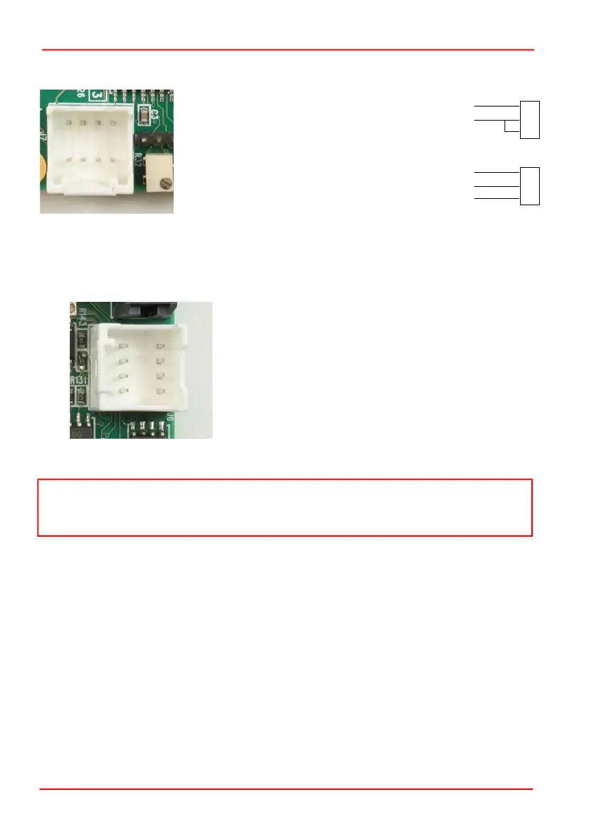
Function
Generator
J7
1
2
7/8
+
-
Function
Generator
J7
1
2
7/8
+
-
Standard O/P
Differential O/P
Earth
Pin 1 Command Input +ve
Pin 2 Command Input -ve
Pin 3 DRV OK
Pin 4 External Enable
Pin 5 -12V Output (low impedence O/P)
Pin 6 +12V Output (low impedence O/P)
Pin 7 Ground
Pin 8 Ground
1
Pin 1 Scanner Position
Pin 2 Internal Command Signal
Pin 3 Positioning Error x 5
Pin 4 Motor Drive Current
Pin 5 Not Connected
Pin 6 Test Input (NC)
Pin 7 Motor + Coil Voltage / 2
Pin 8 Ground
2
3
4
8
7
6
5
 Loading...