© 2019 Thorlabs6
PDB48xC-AC
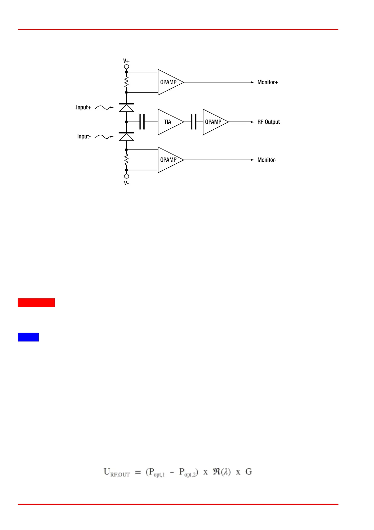
Below is a functional block diagram of the PDB48xC-AC Balanced Amplified Photodetectors:
3.2 Optical Inputs
The PDB48xC-AC comes with fiber-coupled optical inputs. Both photo detectors are SMF28
(PDB480C-AC) resp. HI1060 (PDB481C-AC) pigtailed and FC/APC connectorized. For this
reason, a free space beam coupling directly to the PDB48xC-AC is not possible
The PDB48xC-AC can be used in balanced mode (both inputs are illuminated) as well as in
single detector mode.
In order to avoid saturation, the output signal level should not exceed the RF output power 1-
dB-compression point.
Attention
The damage threshold of the photo diodes is 10 mW (PDB480C-AC) resp. 5 mW (PDB481C-
AC)! Exceeding this value will permanently destroy the photo diode!
Note
Take care for clean fiber connectors prior to attach them to the PDB48xC-AC's optical inputs!
Clean and dust free connections are essential to minimize coupling loss and back reflections.
3.3 Electrical Outputs
The Thorlabs PDB48xC-AC has three SMA output connectors:
· MONITOR +
· MONITOR -
· RF OUTPUT
RF OUTPUT delivers an output voltage proportional to the difference between the photo cur-
rents of the two photodiodes This voltage can by calculated to:
with:
Â
(
l
) - responsivity of the photo diode at given wavelength

 Loading...