PAGE 2 of 7
M300 SERIES
01A-02-D4
002 02/96
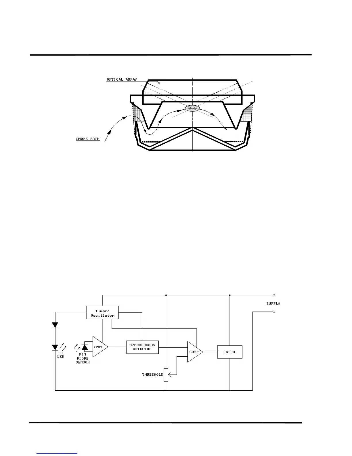
Fig. 2 Measuring Chamber Showing Smoke Flow Path
2.3 CIRCUIT OPERATIONS
A simplified block schematic of the detector is given in
Fig.3.
2.3.1 GENERAL
The GaAs emitter is pulsed every 10s in order to reduce its
power consumption. The pulse signal, as received by the sil-
icon photodiode, is fed to a high-gain amplifier. If smoke is
present, the pulse signal received varies in proportion to the
smoke density. The output of the amplifier is thus propor-
tional to the smoke density.
Detectors in the MR300 Range use the unique measuring
chamber shown in Fig.2.
The Sampling Volume is enclosed within a measuring cham-
ber formed by conical labyrinth mouldings. The optical de-
sign of the chamber provides a very low background signal
in clean air conditions even when the chamber is contami-
nated by white dust. This high tolerance to dust is improved
even further by an aerodynamic design which encourages
dust settlement to occur on the less critical optical surfaces.
The design of the measuring chamber is patented in the UK
under the number GB 2170597 and in the USA under the
number US 4728801.
Fig. 3 Schematic Diagram of Detector