EasyManua.ls Logo

Thule HITCHING POST PRO 934 User Manual

Thule HITCHING POST PRO 934
7 pages
To Next Page IconTo Next Page
Page #1 background imageLoading...
Page #1 background image
934/935/936/937/951xt HITCHING POST PRO
TM
PARTS INCLUDED•PIÈCES INCLUSESPIEZAS INCLUIDAS
Upright/Bike Arm Assembly / Ensemble du montant droit et les bras pour vélos / Ensamblaje del vertical y los brazos para bicicletas
Stinger 2" / Support de 5 cm (2 po) / Soporte de 5 cm (2 pulgadas)
Stinger 1-1/4" / Support de 3 cm (1-1/4 po) / Soporte de 3 cm (1-1/4 pulgadas)
Hitch Tool / Outil d'attelage / Herramienta de enganche
M12x40 Receiver Bolt / Vis du récepteur M12x40 / Perno de receptor M12 x 40
M12 Washer / Rondelle M12 / Arandela M12
M12 Lock Washer / Rondelle de blocage M12 / Arandela de seguridad M12
M8 x 70 Hex Bolt / Vis hexagonale M8 x 70 / Perno hexagonal M8 x 70
M8 Washer / Rondelle M8 / Arandela M8
M8 Lock Nut / Contre-écrou M8 / Contratuerca M8
T3 Cradle Body / Corps de berceau T3 / Cuerpo de cuna T3
T3 Strap Assembly / Ensemble de sangle T3 / Ensamblaje de correa T3
(4/5 Bike) Strap / Sangle (4/5 vélos) / Correa (4 ó 5 bicicletas)
(2 Bike) Strap / Sangle (2 vélos) / Correa (2 bicicletas)
A
B
C
D
E
F
G
H
I
J
K
L
M
1
1
-
2
1
1
1
1
2
1
8
8
1
-
part
pièce
parte
–––
–––
–––
853-5524
908-1240-11
951-1224-11
956-1221-11
908-0870-11
938-0800-11
853-5829
753-3535
753-2030-07
753-2030-08
description
description
descripcion
part number
numéro de pièce
numero de parte
934/935 qty.
934/935 qté
934/935 cant.
1
-
1
2
1
1
1
1
2
1
4
4
-
1
1
1
-
2
1
1
1
1
2
1
10
10
1
-
936/937 qty.
936/937 qté
936/937 cant.
951 qty.
951 qté
951 cant.
A
B
C
D
E
K
F
G
H
I
J
L M
Question and Answer IconNeed help?

Do you have a question about the Thule HITCHING POST PRO 934 and is the answer not in the manual?

Thule HITCHING POST PRO 934 Specifications

General IconGeneral
BrandThule
ModelHITCHING POST PRO 934
CategoryAutomobile Accessories
LanguageEnglish

Summary

Parts Included

Warnings and Limitations

Step 1: Position Stinger into Cradle

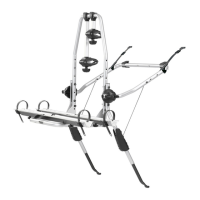
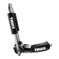
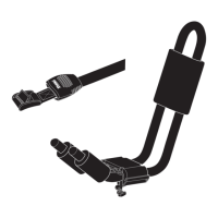
Position the stinger into the cradle of the upper assembly as shown.

Step 2: Assemble 8mm Hardware

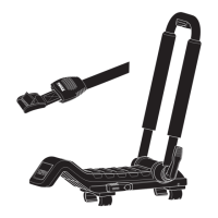
Assemble 8mm hex bolt, 8mm washers and 8mm locking nut as illustrated.

Installation Steps

Step 3: Install Hitch into Receiver

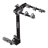
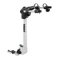
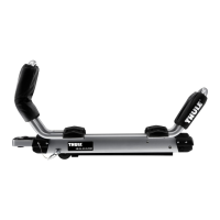
Slide hitch into receiver, secure with M12 bolt, washer, and lock washer.

Step 4: Position Bike Arm Assembly

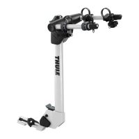
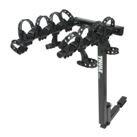
Position bike arm assembly in upright position as illustrated.

Step 5: Load Heaviest Bike First

Load heaviest bike first onto the inner most cradles for optimal weight distribution.

Step 6: Adjust Cradles for Bike Geometry

Rotate or shift cradles on bars to accommodate different bike geometries.

Step 7: Secure Bike Straps

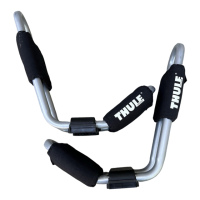
Ensure straps are tightened securely around bike frame.

Step 8: Secure Bikes Together

Use the long strap with cam buckle to secure bicycles together.

Step 9: Rear Compartment Access

Instructions for accessing the rear compartment.

Step 10: Lower Carrier

Gently lower carrier to the built-in stop position.

Security and Accessories

Using Snug Tight Lock

Lock the carrier to the vehicle hitch using the Snug Tight Lock.

Using Cable Lock for Bikes

Lock bikes to the carrier using a cable lock and the built-in locking eye.

Anti-Sway Cage Accessory

Use the 955 No Sway Cage accessory to limit bike swinging.

Thule Rack Guidelines

General Usage Precautions

Ensure all parts are secure, check for wear, and obey traffic laws.

Maintenance and Warranty

Remove rack when not in use, consult dealer for questions, and understand warranty limits.

Related product manuals