Do you have a question about the THUNDER TIGER ST-1 PRO and is the answer not in the manual?
Choose a fuel from a reputable, brand name company that is approved for car/truck use.
For proper engine break-in procedure, please refer to the manual of your engine.
When turning radio on, first turn on the transmitter and extend the transmitter antenna.
If you drink nitro fuel by accident, immediately drink large quantities of water and try to induce vomiting.
Improper operations may cause personal and/or property damage. Thunder Tiger and its distributor have no control over damage.
AA-Size Batteries for transmitter / NiCd or NiMh Battery recommended.
Glow Fuel, Fuel Bottle, Glow Starter, Air Filter Oil.
Phillips type screwdrivers & hex wrenches, Needle Nose Pliers, Lexan Cutter/Scissors.
CA Glue, Thread Locking Glue, Silicon Oil, Lexan Specific Spray Paint.
Hex Wrench, Wrench, 5-way Nut Wrench W/EXT Tool.
Part bag used, Apply C.A Glue, Apply Grease, Apply silicon oil, Apply thread locking glue.
Assembly of steering bell-crank with bearing.
Assembly of servo tie rod and steering rod with left/right threads.
Assembly of front torque rod and steering components.
Assembly of carbon plate for camber adjustment with hex screws.
Assembly of differential gears with O-rings and shims.
Filling differential cases with silicone oil for front, center, and rear.
Hint for using shims to adjust backlash on front and rear bulkheads.
Assembly of front and rear shock towers using various screws.
Assembly of brake pads and disks for the center differential mount.
Optional parts for center differential mount and heatsink disc brake.
Assembly of rear chassis components including suspension arm holders.
Assembly of front chassis components including suspension arm holders.
Assembly of front suspension parts including bearings and pins.
Assembly of front suspension arms with set screws and hex screws.
Adjustment of front suspension geometry using shims and hex screws.
Assembly of optional sway bars and upper arm plates.
Assembly of front shock towers and track width adjustment.
Assembly of rear suspension parts including bearings and pins.
Assembly of rear suspension arms with set screws and hex screws.
Tightening set screws on hinge pins for rear suspension.
Note orientation for wheelbase adjustment spacers.
Assembly of rear suspension holders and optional parts.
Assembly of rear hub position and upright pin position.
Initial position of rear suspension on the shock tower.
Initial position of rear suspension on the rear hub.
Assembly of radio box and fuel tank, including optional parts.
Assembly of engine mount with fixing screws and lock nuts.
Hint for proper gear mesh adjustment using paper.
Note orientation of clutch shoes and engine rotation direction.
Cutting throttle rod and excess linkage to avoid interference.
Installation of servo horns and linkage for throttle and brake control.
Adjusting neutral, high throttle, and brake settings for optimal performance.
Placing silicon oil on shaft tip and diaphragm in shock cup.
Recommended shock silicon oil grades and filling shock bodies.
Adjusting shock ride height using clips and hex screws.
Initial front and rear shock positions with socket head hex screws.
Assembly of rear wing posts and marked 'R' components.
Assembly of rear wing components and marked 'L' components.
Adjusting front toe angle by tuning the length of the steering rod.
Adjusting rear toe angle by changing toe blocks and plastic balls.
Adjusting caster angle by changing plastic clips in the front upper hinge pin.
Adjusting front anti-squat angle using eccentric bushings.
Adjusting rear anti-squat by replacing rear suspension holders.
Adjusting front camber by changing pivot ball lengths in upper arms.
Adjusting rear camber by adjusting lengths of upper tie rods.
Adjusting front/rear ride height by screwing/unscrewing setscrews.
Adjusting Ackerman angle by linking front steering rods to steering slider.
Selection of front and rear suspension holders (FF-1, FF0, FF1, RF0, RF2, RF3, RF4, RR1, RR1.5, RR2, RR3).
Options for front (A) and rear (B) steering plates.
Options for sway bar diameters in Gold, Black, and Silver.
Adjusting track width for optimal performance.
Options for adjusting wheelbase using spacers (1mm, 2mm, 3mm).
Adjusting front caster using spacers up to 5mm.
Selection of track surface (Smooth/Bumpy) and traction (Low/Med/High).
| Brand | THUNDER TIGER |
|---|---|
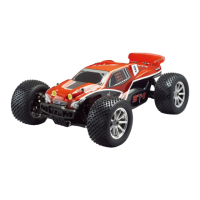
| Model | ST-1 PRO |
| Category | Motorized Toy Car |
| Language | English |