6
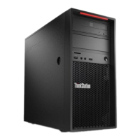
5. Install the Thunderbolt I/O adapter card onto the retaining bracket by aligning the four
locator holes with the corresponding mounting posts on the bracket. Press down on the
card until the four retaining clips snap into place, securely mating the two parts into a
single assembly.
6. Install the retaining bracket/adapter card assembly into the FLEX module by reversing the
procedure performed in step 4. Slide the assembly forward until the retention clip snaps
into place.
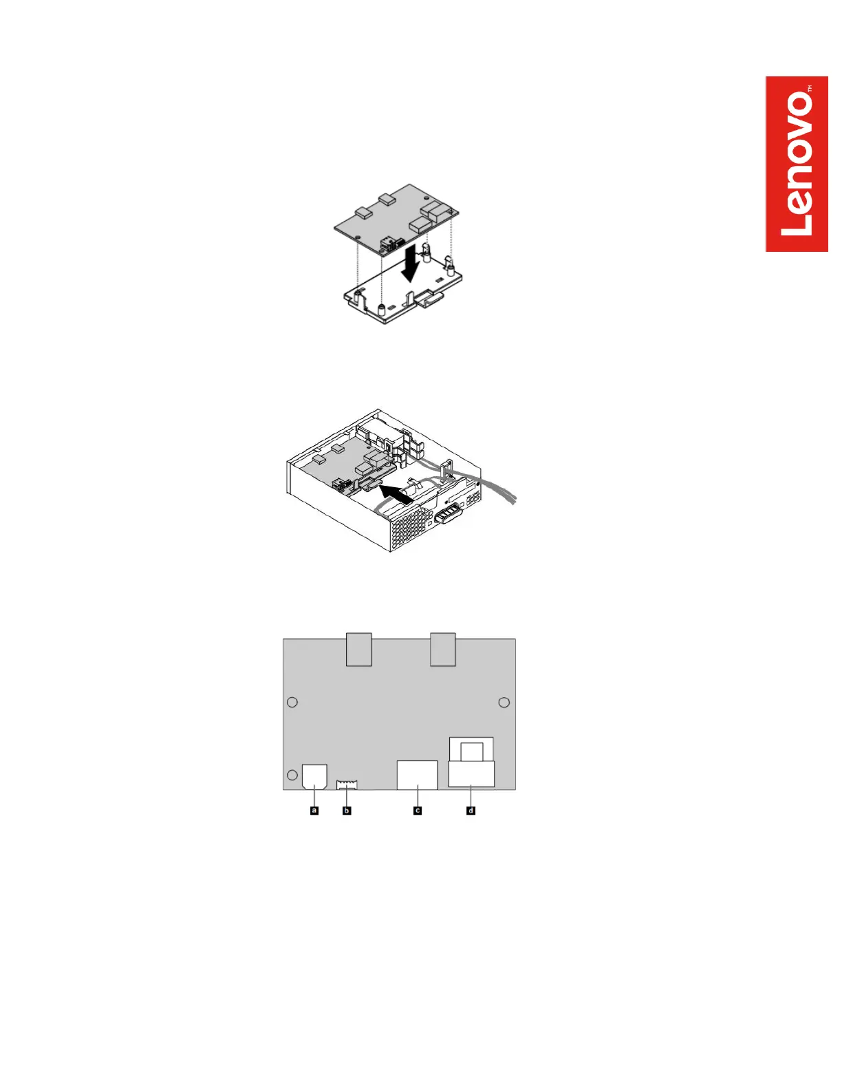
7. Plug four cables into the rear of the adapter card. The power cable is already part of the
FLEX module and the remaining 3 cables were supplied with the Thunderbolt 3 kit. Use
the following connector layout diagram as a guide for cable connections:
a – Power cable connector
b – GPIO cable connector
c – Internal DP to DP cable connector
d – mini-SAS cable connector
Note: The power cable is integrated into the FLEX module, originating from the rear
power connector. The other 3 cables are supplied as part of the Thunderbolt 3 kit.