5
Installation instructions (front port solution)
Note: Due to differences in chassis design, portions of this installation procedure will vary
depending on the type of workstation you have (P520c, P520, P720, or P920). Where
necessary, the installation procedure differences are noted below.
FLEX module preparation
1. The FLEX module is designed with the removable access cover on the bottom. Invert the
FLEX module so that the removable cover is facing up and then place it on a flat work
surface. Lift the metal tab on the rear of the module and slide the cover back and up to
remove it from the module.
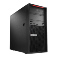
2. When viewed from the front, the FLEX module faceplate has slots for 4 devices or ports.
The Thunderbolt 3 ports will be installed in the top right slot (with the module oriented as
shown below), which is currently filled by a blank bezel. Remove the blank bezel by
pressing the two internal retaining tabs and popping the bezel out the front of the
faceplate.
3. Install the Thunderbolt 3 bezel in the empty faceplate slot. The bezel should be oriented
so that the Thunderbolt 3 icons are below the port openings in its current orientation. The
module will be flipped over before it is inserted into the workstation, so these icons will be
above the ports in the final orientation. Press the bezel from the front until the retaining
tabs snap into place.
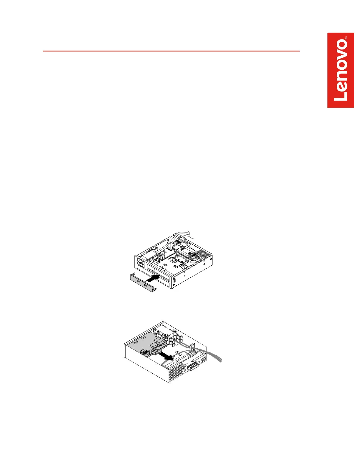
4. Remove the card retaining bracket from the FLEX module by lifting the retention clip
slightly and sliding the bracket toward the rear of the module.