Page 5For technical questions, please call 1-888-866-5797.Item 57325
SAFETYOPERATIONMAINTENANCE SETUP
Specifications
Rated Output 18 VDC / 100 W / 5.56A
Note: Performance will vary depending on temperature, brightness and time of sun exposure. Summer
production will be higher than in the winter. Bright sunny days will generate higher output than cloudy days.
Set Up Instructions
Read the ENTIRE IMPORTANT SAFETY INSTRUCTIONS section at the beginning of this manual
including all text under subheadings therein before set up or use of this product.
TO PREVENT SERIOUS INJURY FROM ACCIDENTAL OPERATION:
Make sure that the Power Switch/Trigger is in the off-position and unplug the tool
from its electrical outlet before performing any procedure in this section.
Note: For additional information regarding the parts listed in the following pages,
refer to the Assembly Diagram near the end of this manual.
Installation
Location
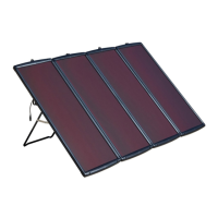
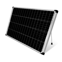
1. Locate the Solar Panel where it will receive full,
unobstructed sunlight, especially during midday.
Nearby trees or tall plants will drop debris, requiring
the panels to be cleaned more frequently.
2. The installation location for the Solar Panel,
charge controller/regulator, and batteries must
be inaccessible to children to prevent electric
shock. Build a childproof enclosure if needed.
3. Install the charge controller/regulator and batteries
in a weatherproof enclosure with proper ventilation.
Setup
This Solar Panel can be setup
temporarily or permanently.
1. Use the two pull-out Mounting Stands on
the rear panel for temporary setup.
Note: Avoid temporary set up on windy or stormy days.
2. For permanent setup, use appropriate
mounting hardware (sold separately) to
connect the Solar Panel to selected surface
using the predrilled holes in the corners of the
panel. Do not drill additional holes in panel.
3. Angle the face of the Solar Panel toward
true south according to chart below:
Latitude Solar Panel Angle
0-4° 10°
5-20° Latitude + 5°
21-45° Latitude + 10°
46-64° Latitude + 15°
65° or more 80°
Wiring
Note: Only a licensed electrician and a licensed
building contractor can safely design and implement a
grid tie-in system. Any grid tie-in system must meet all
applicable building and electrical codes, and must meet
standards established by the area power company.
1. Run wires from panels, through weatherproof
grommets and into enclosure where power
inverter is located. Use wires of the proper
size and rating and use twist connectors
(not included) to connect wires.
2. Connect battery to a power inverter according
to inverter’s instructions. CAUTION! Inverter
must be properly rated and designed for this
type of connection and power supply.
3. Secure all connections using terminals, or solder
all wire splices to ensure good connections.
4. Weatherproof all connections and route the wire in
a way that it will not be torn loose from the panel.
 Loading...