FUNCTION CHARACTERISTICS
50
NG10 - Manual - 04 - 2022
t
>RES
T0
RESET
t
E>
0T
t
E>def
t
E>inv
t
E>RES
Start IE>
Trip IE>
ON≡ Inhibit
(from IE>> and/or IE>>> residual overcurrent element)
ON≡ Enable IE> residual overcurrent element
IE> inhibition
&
BF Enable (ON≡ Enable)
IE>BF
towards BF logic
IE> BF
&
Trip IE>
TRIPPING MATRIX
(LED+RELAYS)
I
E
> Curve
0T
IE> Enable
I
E
>TR-K
I
E
>TR-L
I
E
>ST-L
I
E
>ST-K
I
E
≥ 1
(Pickup outside CLP)
&
State
I
E
>
inv
I
E
≥
I
E
>
def
I
E
≥
I
E
>
inv
I
E
>
def
&
State
Binary input INx
T 0
Logic
INx
t
ON
INx
t
ON
INx
t
OFF
T0
n.o.
n.c.
INx
t
OFF
Binary input INx
T 0
Logic
INx
t
ON
INx
t
ON
INx
t
OFF
T0
n.o.
n.c.
INx
t
OFF
Binary input INx
T 0
Logic
INx
t
ON
INx
t
ON
INx
t
OFF
T0
n.o.
n.c.
INx
t
OFF
Block2 IPh
Block2 IPh/IE
ModeBLIN1
T 0
t
B-Iph
≥ 1
≥ 1
≥ 1
≥ 1
≥ 1
t
B-Iph
t
B-IE
&
IE>BLK1
Block2 input enable (ON≡ Enable)
Pilot wire input
&
IE>BLK2IN
BLK2IN-Iph
Start IE>
Trip IE>
Iph Block2
IE Block2
BLK2IN-IE
tB timeout
Block2 input
Block2 output
tB-K
tB-L
FROM GROUND PROTECTIONS
FROM ANY PROTECTIONS
FROM PHASE PROTECTIONS
OFF
ON IPh
ON IPh/IE
ON IE
BLIN1
T 0
t
B-IE
Block2 IE
TRIPPING MATRIX
(LED+RELAYS)
≥ 1
≥ 1
Binary input INx (x=1,2)
T 0
Logic
INx
t
ON
INx
t
ON
INx
t
OFF
T0
n.o.
n.c.
INx
t
OFF
BLK1 IE>
&
BLK2IN IE>
&
&
Enable (ON≡ Enable)
Block1
Block1
Block2
Block1
Block1
Block1, Block2
See function diagram on next page
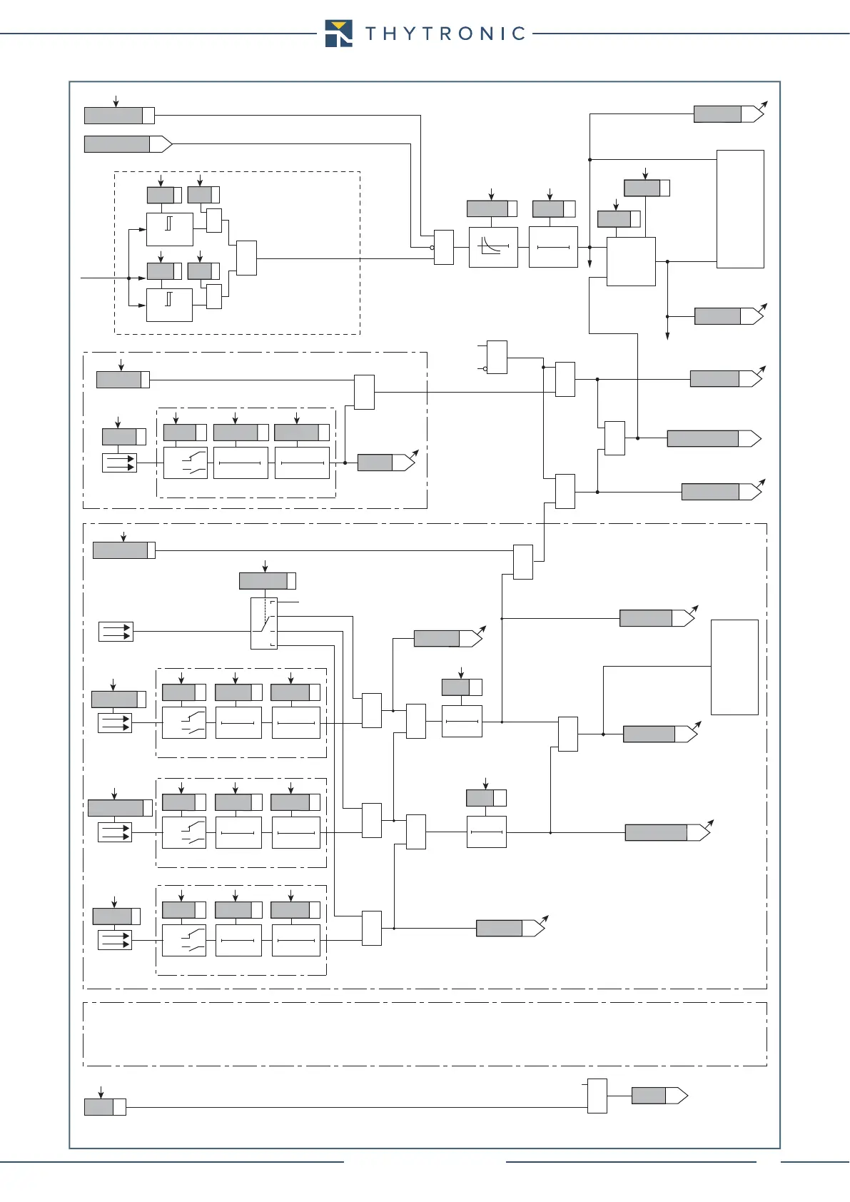
Residual overcurrent or high impedande differential restricted ground fault (50N/51N-87NHIZ) - Logic diagram concerning the first element