APPENDIX
131
NG10 - Manual - 04 - 2022
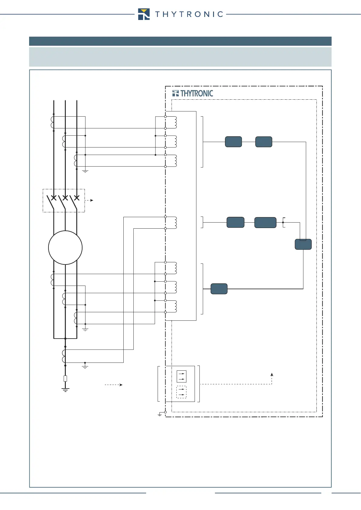
8.6 APPENDIX B3- Connection diagrams
Note: Some typical connection diagram are shown.
All diagram must be considered just as example; they cannot be comprehensive for real applications.
For all diagrams the output contacts are shown in de-energized state for standard reference.
87T
CB position
NG10
SIDE H
BINARY INPUTS
CB position
BF
SIDE L CURRENT INPUTS
L1 L2 L3
Differential protection of generator
C10
C9
C11
C12
C13
C14
P1
S1
S2
P2
I
L1L
I
L2L
I
L3L
C2
C1
C3
C4
C5
C6
P1
S1
S2
P2
I
L1H
I
L2H
I
L3H
C15
C16
I
E
50N/51N
BF
74CT
64REF
74CT
P1
S1
S2
P2
P1
S1
S2
P2
G
NOTE
- To current with incoming direction in the protected component must match incoming current in the reference terminals of of the relay current inputs ,
while to current having a outgoing direction from the protected component must match output current in the reference terminals of the current inputs
of the relay.
- The input current in the reference terminals of of the relay current inputs of the are considered positive, negative for outgoing ones.
- This Convention applies: the CTs polarity P1 to the protected component.