118
FUNCTION CHARACTERISTICS
pickup value are detected and a start is issued when the following conditions are met:
• The circuit breaker is closed (if the control is enabled)
• The t
ARM-Q
< adjustable timer has expired started from the CB closure
If all conditions are still met, after expiry of the associated operate time (t
Q1
<
def,
t
Q2
<
def
) a trip command
is issued; if instead the power drops below the threshold, the element is restored.
The elements can be enabled or disabled by setting ON or OFF the State parameter inside the Set
\ Profile A (or B) \ Directional reactive underpower-37Q \ Q1< Element (Q2< Element) \ Definite time
menu..
Enabling of the CB state control (ON or OFF of the
CB-37Qparameter) and adjustment of the wai-
ting time following the CB closing (
tARM-Q<parameter) maj be adjusted inside the Set \ Profile A
(or B) \ Directional reactive underpower-37Q \ Q1< Element (Q2< Element) \ Common configuration
menu.
The elements can be enabled or disabled by setting ON or OFF the State parameter inside the Set
\ Profile A (or B) \ Directional reactive underpower-37Q \ Q1< Element (Q2< Element) \ Definite time
menu.
VT supervision (74VT)
The protection element is blocked off whenever the VT or/and CT supervision function are active,
so that no unwanted trip can arise if any fault on the VTs or/and CTs secondary circuits (break, fuse
trip, etc) are detect;
1
the Block functions enable from 74VT and 74CT parameter (74VT-BK-ENand
74CT-BK-EN) are available inside the Set \ VT supervision -74VT, and Set \ CT supervision -74CT menus.
Breaker failure (BF)
Each thresholds (Q1<, Q2<) can be associated to BF (H) and BF (L) protection by activating the rel-
ative parameter in the matrices “Selection of function tripping for BF (H)” or “Selection of function
tripping for BF (L)” in relevant BF menus
2
:
• Set \ Profile A (or B) \ Breaker failure - BF side H
• Set \ Profile A (or B) \ Breaker failure - BF side L
Logical block (Block1)
If the Q1<BLK1 and/or Q1<BLK1 enabling parameters is set to ON and a binary input is designed
for logical block (Block1), the protection is blocked whenever the given input is active.
The trip timer is held in reset condition, so the operate time counting starts when the input block goes
down.
3
The enabling parameters are available inside the Set \ Profile A (or B) \ Directional reactive
underpower - 37Q \ Q1< Element Q2< Element) \ Setpoints menu, while the Block1 function must be
assigned to the selected binary input inside the Set \ Board 1(2) inputs \ Binary input IN1-1...(IN1-x)
menus.
All parameters can be set separately for A and B setting profiles.
Note 1 The exhaustive treatment of the VT and CT supervision function may be found inside the CONTROL AND MONITORING section.
Note 2 The common settings concerning the Breaker failure protection are adjustable inside the Breaker Failure - BF menu.
Note 3 The exhaustive treatment of the logical block (Block 1) function may be found in the “Logic Block” paragraph inside CONTROL AND MONITOR-
ING section.
Q
Q
1
<
t
t
P1
<
TRIP
Q
1
<
TRIP
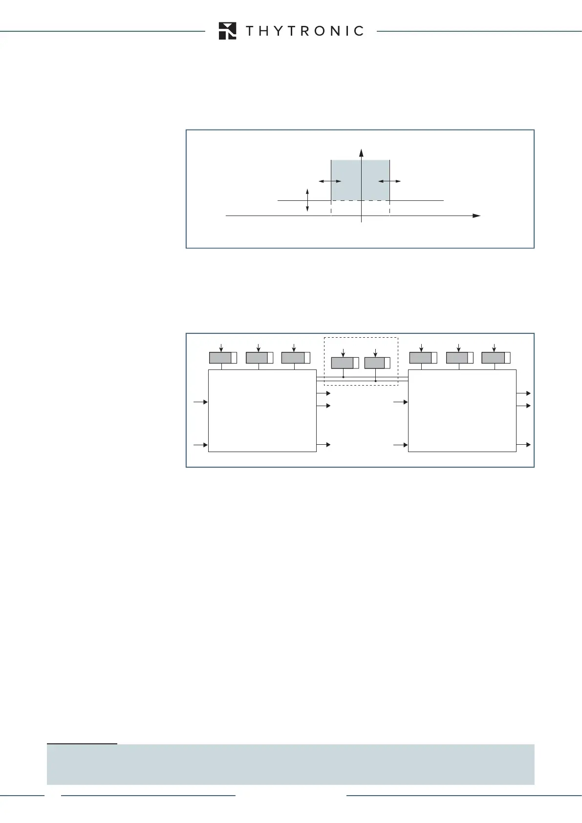
General operation time characteristic for the directional reactive power element - 32Q (first element)
2nd Pickup Element
Block1
Block1
P
Q
2
< Start
Q
2
< Trip
1st Pickup Element
Common
Block1
Block1
Q
Q
1
< Start
Q
1
< Trip
Q
1<DIR
Q1<def
t
Q1
<def
Q
2<DIR
CB-37Q
t
ARM-Q<
Q2<def
t
Q2
<def
General operation time characteristic for the directional reactive underpower elements - 37Q
XMR-D EQUIPMENT MANUAL
Ed. 2.9 - 02/2021
 Loading...
