124
FUNCTION CHARACTERISTICS
• For both trip thresholds (t
XC1XD1RES
, t
XC2XD2RES
) a reset time delay may be adjusted in order to
protect against the out of step of low size generators connect to high short circuit impedance grids.
Breaker failure (BF)
Each thresholds (XC1XD1, XC2XD2) can be associated to BF (H) and BF (L) protection by activating
the relative parameter in the matrices “Selection of function tripping for BF (H)” or “Selection of
function tripping for BF (L)” in relevant BF menus
[1]
:
• Set \ Profile A (or B) \ Breaker failure - BF side H
• Set \ Profile A (or B) \ Breaker failure - BF side L
Logical block (Block1)
If the XC1XD1-BLK1and/orXC2XD2-BLK1) enabling parameters are set to ON and a binary in-
put is designed for logical block (Block1), the concerning element is blocked off whenever the given
input is active.
[2]
The enabling parameter is available inside the Set \ Profile A (or B) \ Loss of field - 40
\ XC1-XD1, XC2-XD2 Element menus, while the Block1 function must be assigned to the selected
binary input inside the Set \ Board1(2) inputs \ Binary input IN1-1...INx-x menus.
All the named parameters can be set separately for Profile A and Profile B.
Block3
The 40 element is disabled when:
• the phase voltages U
L1
is lower than 10% E
n
or
• the phase currents I
L1
is lower than 5% I
n
or
• the measured frequency becomes lower than 20 Hz or higher than 70 Hz or
• all the phase voltages U
L1
, U
L2
, U
L3
are lower than 1% E
n
or
• all the phase currents I
L1
, I
L2
, I
L3
are lower than 15% I
n
Note 1 The common settings concerning the Breaker failure protection are adjustable inside the Breaker Failure - BF menu.
Note 2 The exhaustive treatment of the logical block (Block 1) function may be found in the “Logic Block” paragraph inside CONTROL AND MONITOR-
ING section
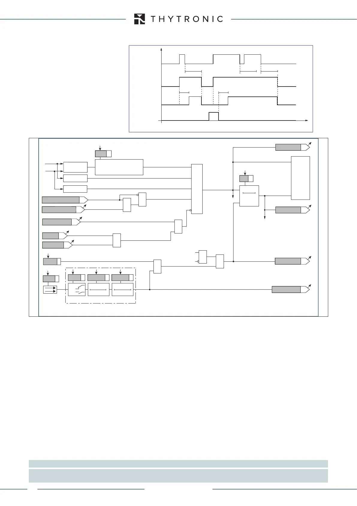
Timers-F40.ai
Timers concerning the first threshold of the loss of field element -40
X
O1
-X
D1
Start
X
O1
-X
D1
Trip
RESET
INPUT
t
XC1XD1RES
t
XC1XD1
t
XC1XD1
t
XC1XD1RES
t
XC1XD1RES
t
Fun-40_AL.ai
I
L1L
U
L1
Z
1
,
R
,
X
X ≤ tanAlpha · R & R ≤ 0
or
X ≤ -tanAlpha · R & R > 0
U
L1
≥ 10%U
n
I
L1
≥ 5%I
nL
&
Alpha
RESET
t
AL
<
0T
TRIPPING MATRIX
(LED+RELAYS)
t
AL
<
Alpha
Start
Alpha
Start
Alpha
Start
Alpha
Trip
Alpha
Trip
Alpha
Trip
Block3
74VT Block
VT fault (74VT)
Alpha
Block1
&
&
&
Enable (ON≡Enable)
Block1 input (ON≡Block)
Block1
Block1
(=0 without fault)
=0 if 20≤f≤70 Hz
Block1
Alpha inhibition
from
(
X
O1
-X
D1
) and/or
(
X
O2
-X
D2
)
element (ON≡Inhibit)
≥1
≥1
≥1
Start undervoltage
&
Undervoltage enable
(ON≡Enable)
Binary input INx
T 0
Logic
INx
t
ON
INx
t
ON
INx
t
OFF
T0
n.o.
n.c.
INx
t
OFF
Logic diagram concerning the Alarm threshold of the loss of field element - 40
XMR-D EQUIPMENT MANUAL
Ed. 2.9 - 02/2021
 Loading...
