134
FUNCTION CHARACTERISTICS
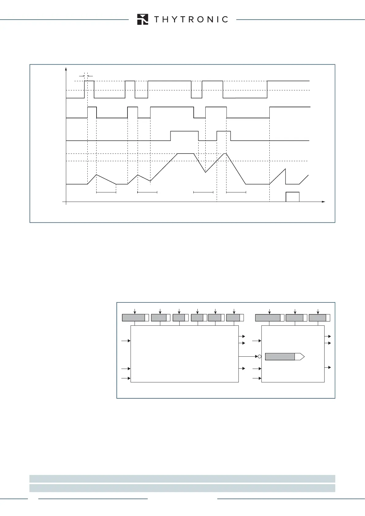
The alarm threshold has a definite time characteristic.
If the inverse sequence current drops below the threshold, the element it is restored after a delay
time t = K
cool
/(I
2
>>/I
B
)
2
; in this way, the device makes use of a memory which allows the integration
of subsequent periods of excess and relapse of the trip threshold prior to reaching the trip time.
The maximum (t
2max
) and minimum (t
2min
) operating time are adjustable; the counter may be cleared
by means an external command (serial communication, MMI or binary input).
The
ResettimerI2 function must be assigned to the selected binary inputs inside the Set \ Board
1(2) inputs \ Binary input IN1-1...(IN1-x) menus.
All overcurrent elements can be enabled or disabled by setting ON or OFF the
I2AL>Enable and/
or
I2>>Enableparameters inside the Set \ Profile A (or B) \ Negative sequence overcurrent - 46G
\ I2> Element (I2>> Element) menus.
The trip of I
2AL
> element may be inhibited by the start of the second element (I
2
>>) by set-
ting ON the Disabling I2> by start I2>> (I2>disbyI2>>) parameter available inside the
Set \ Profile A (or B) \ Negative sequence overcurrent-46G \ I2>> Element menu.
All the parameters can be set separately for Profile A and Profile B menus.
Breaker failure (BF)
Each thresholds (I2AL>, I2>>) can be associated to BF (H) and BF (L) protection by activating the
relative parameter in the matrices “Selection of function tripping for BF (H)” or “Selection of function
tripping for BF (L)” in relevant BF menus
[1]
:
• Set \ Profile A (or B) \ Breaker failure - BF side H
• Set \ Profile A (or B) \ Breaker failure - BF side L
CT supervision (74CT)
The protection element is blocked off whenever the CT supervision function is active, so that no
unwanted trip can arise if any fault on the CTs secondary circuits are detect;
[2]
Note 1 The common settings concerning the Breaker failure protection are adjustable inside the Breaker Failure - BF menu.
Note 2 The exhaustive treatment of the VT and CT supervision function may be found inside the CONTROL AND MONITORING section.
Operating time for the negative sequence overcurrent element - 46G
Start I
2
>>
Trip I
2
>>
RESET
Conteggio
temporizzatore
I
2
>>
I
2
I
B
t
START
t
t
2MAX
K
heat
K
cool
K
cool
K
cool
K
cool
all-F21.ai
I
2
>> Element
I
2AL
Element
Block1
Block1
I
2
I
2
Block3
Block1
Block3
Block1
I
2
>>
Enable
I
2AL
>
Enable
I
2
>>
inv
t
2MIN
K
heat
K
cool
t
2MAX
I
2AL>def
t
2AL>def
I
2AL
> inhibition
I
2
>>
Start
I
2
>>
Trip
I
2
>>
Trip
I
2AL
>
Start
I
2AL
>
Trip
Logic diagram concerning the negative sequence overcurrent element - 46G
XMR-D EQUIPMENT MANUAL
Ed. 2.9 - 02/2021
 Loading...
