158
FUNCTION CHARACTERISTICS
When the thermal image Dq overcomes the threshold (e..g.Dq> = 1.2 Dq
B
corresponding to a thermal
equivalent current of 1.1I
B
), a trip is issued.
Following data applies for the [1]:
• Range where the equation is valid: 1.1I
B
≤ I
th
≤ 10I
B
• If 10I
B
≤ I
th
≤ 20I
B
, the operating time is fixed to a value corresponding to the 10I
B
• The upper limit is 20I
B
.
If the CLP function (Cold Load Pick-up) is enabled for element blocking, the element may be blocked
for an adjustable time interval, starting from the starting control criterion (circuit breaker closure or
I
RUN
threshold).
This operating mode may be select by setting
ON-Elementblockingthe DThCLPMode parame-
ter inside the Set \ Profile A (or B) \ Thermal image-49MG \ Common configuration menu.
If the CLP function (Cold Load Pick-up) is enabled for setting change, the equivalent thermal current
may be reduced by a K
ST
starting overload coefficient for an adjustable time interval, starting from
the starting control criterion (circuit breaker closure or I
RUN
threshold).
This operating mode may be select by setting
ON-Changesettingthe DThCLPMode parameter
inside the Set \ Profile A (or B) \ Thermal image-49MG \ Common configuration menu.
For both operating modes the DThCLP Activation time (tDThCLP) may be adjusted inside the Set \
Profile A (or B) \ Thermal image-49MG \ Common configuration menu.
Starting control
If the CLPSourceparameter is set to IRUN and the maximum value of phase currents is lower than
0.1 I
B
, the protection is blocked off or the equivalent thermal current is decreased by a K
ST
starting
overload coefficient depending on the
DThCLPMode setting.
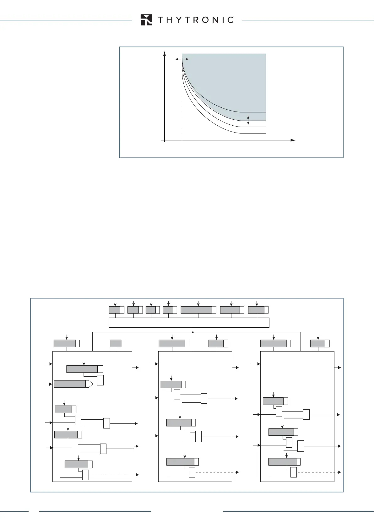
p=0 (Hot curve)
p=1 (Cold curve)
General operation time characteristic for the thermal image elements - 49MG
t-int-F49.ai
I
th
/I
B
√(Dth>/DthetaB)
t
TRIP
all-F49.ai
K
ST
K
2
T+ T- DthIN DthCLP Mode tDthCLP
Common configuration
I
th
Dth> Element
Trip DTh>
DTh> Enable
DTh>
BLK2OUT
Dth>BLK2OUT
&
Trip Dth>
Trip Dth>
BLK2INDth>
Block2
&
Dth
>BLK2IN
&
DthAL1 Element
DThAL1
DThAL1
DThAL1
DThAL1 Enable
I
th
BLK2OUT
DthAL1BLK2OUT
&
Block1
BLK1DthAL1
&
DthAL1BLK1
&
Dth>AL1
DthAL1
BLK2INDthAL1
Block2
&
Dth
AL1BLK2IN
&
DthAL2
BLK2INDthAL2
Block2
&
Dth
AL2BLK2IN
&
DthAL2 Element
DThAL2
DThAL2
DThAL2 Enable
I
th
BLK2OUT
DthAL2BLK2OUT
&
Block1
BLK1DthAL2
&
DthAL2BLK1
&
Dth>AL2
Dth>AL2
Block1
BLK1Dth>
&
Dth>BLK1
Trip Dth>
&
&
50-51 inhibition
Dth>disby50-51
General logic diagram of the thermal image elements - 49MG
XMR-D EQUIPMENT MANUAL
Ed. 2.9 - 02/2021
 Loading...
