FUNCTION CHARACTERISTICS
173
The element can be enabled or disabled by setting ON or OFF the State parameter inside the Set \
Profile A (or B) \ Negative sequence current/positive sequence current ratio-I2/I1 \ I21> Element \ De-
finite time menu.
Breaker failure (BF)
I
2
/I
1
> threshold can be associated to BF (H) and BF (L) protection by activating the relative parameter
in the matrices “Selection of function tripping for BF (H)” or “Selection of function tripping for BF (L)”
in relevant BF menus
1
:
• Set \ Profile A (or B) \ Breaker failure - BF side H
• Set \ Profile A (or B) \ Breaker failure - BF side L
Second harmonic restraint
A block from the second harmonic restraint may be set by setting ON the parameter insi-
de the Set \ Profile A (or B) \ Negative sequence current/positive sequence current ratio-I2/I1 \
I21> Element \ Setpoints menu.
Cold load pickup
If the CLP function (Cold Load Pick-up) is enabled for element blocking, the selected threshold may
be blocked for an adjustable time interval, starting from the circuit breaker closure.
This operating mode may be select by setting
ON-Elementblockingthe I21CLP>Modepara-
meter.
If the CLP function (Cold Load Pick-up) is enabled for threshold change, the selected threshold may
be changed for an adjustable time interval, starting from the circuit breaker closure. This operating
mode may be select by setting
ON-Changesettingthe I21CLP>Modeparameter, whereas the
operating thresholds within the CLP may be adjusted inside the Set \ Profile A (or B) \ Negative se-
quence current/positive sequence current ratio-I2/I1 \ I21> Element \ Definite time menu.
For both operating modes the CLP Activation time parameter (t21CLP>) may be adjusted insi-
de the Set \ Profile A (or B) \ Negative sequence current/positive sequence current ratio-I2/I1 \
I21> Element \ Setpoints menu.
CT Supervision (74CT)
The element may be blocked when the CT supervision function become active to avoid unwanted
trips following any faults on CTs an amperometric input circuits;
2
the 74CTEnableparameter may
be set to ON inside the Set \ CT supervision-74CT menu.
All parameters can be set separately for A and B setting profiles.
Logical block (Block1)
If the I21>BLK1 enabling parameter are set to ON and a binary input is designed for logical block
(Block1), the protection is blocked off whenever the given input is active.
The trip timer is held in reset condition, so the operate time counting starts when the input block
goes down.
3
The enabling parameter is available inside the Set \ Profile A (or B) \ Negative sequence
current/positive sequence current ratio-I2/I1 \ I21> Element \ Setpoints menu, while the Block1
function must be assigned to the selected binary input inside the Set \ Board 1(2) inputs \ Binary input
IN1-1...(IN1-x) menus.
Note 1 The common settings concerning the Breaker failure protection are adjustable inside the Breaker Failure - BF menu.
Note 2 The setting may be found in the “CT supervision ” paragraph inside CONTROL AND MONITORING section
Note 3 The description of the logical block (Block 1) function may be found in the “Logic Block” paragraph inside CONTROL AND MONITORING section
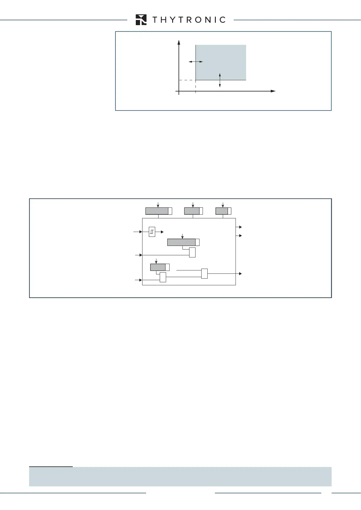
I
2
/I
1
t
21
>
(I
2
/I
1
)>
t
General operation time characteristic for negative sequence-positive sequence ratio element - I2/I1
TRIP
General logic diagram of the negative sequence-positive sequence ratio element - I2/I1
all-FI2-I1.ai
(I2/I1)
(I2/I1)> Element
Start
(I2/I1)>
Start
(I2/I1)>
Trip
(I2/I1)>
t
21
>
def
(I2/I1)>
def
Enable (I2/I1)>
Block1
BLK1
(I2/I1)>
&
I<<BLK1
&
Start I2ndh>
&
(I2/I1)>2ndh-REST
XMR-D EQUIPMENT MANUAL
Ed. 2.9 - 02/2021
 Loading...
