210
FUNCTION CHARACTERISTICS
Similarly the trip of the IE(H)>> element may be inhibited by start of the third element (IE(H)>>>) by
setting ON the Disable IE(H)>> by start IE(H)>>> (IE(H)>>disbyIE(H)>>>) parameter available
inside the Set \ Profile A (or B) \ Calculated residual overcurrent-50N(Comp)/51N(Comp) side H \
IE(H)>>> Element \ Setpoints menus for side H element, the IE(L)>>disbyIE(L)>>> parameter
available inside the Set \ Profile A (or B) \ Calculated residual overcurrent-50N(Comp)/51N(Comp)
side L \ IE(L)>>> Element \ Setpoints menus for side L element and the IE(T)>>disbyIE(T)>>>
parameter available inside the Set \ Profile A (or B) \ Calculated residual overcurrent-50N(Com-
p)/51N(Comp) side T \ IE(T)>>> Element \ Setpoints menus for side T element.
All the parameters can be set separately for Profile A and Profile B
E’ regolabile un tempo di ripristino costante per ciascuna delle soglie (t
E(H)
>
RES
, t
E(H)
>>
RES
,
t
E(H)
>>>
RES
per il lato H e t
E(L)
>
RES
, t
E(L)
>>
RES
, t
E(L)
>>>
RES
per il lato L).
Breaker failure (BF)
Each thresholds (IEC>, IEC>>, IEC>>>) can be associated to BF (H) and BF (L) protection by activating
the relative parameter in the matrices “Selection of function tripping for BF (H)” or “Selection of
function tripping for BF (L)” in relevant BF menus
[1]
:
• Set \ Profile A (or B) \ Breaker failure - BF side H
• Set \ Profile A (or B) \ Breaker failure - BF side L
Second harmonic restraint
For all elements, a block from the second harmonic restraint may be set by setting ON the IEC>2n-
dh-REST,IEC>>2ndh-REST,IEC>>>2ndh-REST.
The parameters are available inside the Set \ Profile A (or B) \ Residual overcurrent-50N(Com-
p)/51N(Comp) \ IEC> Element (IEC>> Element, IEC>>> Element) \ Setpoints menus.
Cold load pickup (CLP)
If the CLP function (Cold Load Pick-up) is enabled for element blocking, the element may be blocked
for an adjustable time interval, starting from circuit breaker closure.
If the CLP function (Cold Load Pick-up) is enabled for setting change, the selected threshold may be
changed for an adjustable time interval, starting from the circuit breaker closure.
The operating mode may be select by setting
ON-Elementblockingor ON-Changesetting the
IECCLP>Mode,IECCLP>>Mode,IECCLP>>>Mode parameter.
The operating modes and the CLP Activation time parameters (
tECCLP>, tECCLP>> e tEC-
CLP>>>) may be adjusted inside the Set \ Profile A (or B) \ Residual overcurrent-50N(Com-
p)/51N(Comp) \ IEC> Element (IEC>> Element, IEC>>> Element) \ Setpoints menus.
The threshold inside CLP (
IECCLP>def,IECCLP>inv,....) can be set inside the Set \ Profile A (or B)
\ Residual overcurrent-50N(Comp)/51N(Comp) \ IEC> Element (IEC>> Element, IEC>>> Element) \ De-
finite time (Inverse time) menus.
For every of the four thresholds the following block criteria are available:
Logical block (Block1)
If the IEC>BLK1,IEC>>BLK1and/orIEC>>>BLK1 enabling parameters are set to ON and a bi-
nary input is designed for logical block (Block1), the concerning element is blocked off whenever the
given input is active.
[2]
The enabling parameters are available inside the Set \ Profile A (or B) \ Resi-
dual overcurrent-50N(Comp)/51N(Comp) \ IEC> Element (IEC>> Element, IEC>>> Element) \ Setpoints
menus, while the Block1 function must be assigned to the selected binary input inside the Set \
Board1(2) inputs \ Binary input IN1-1...INx-x) menus .
Selective block (Block2)
All along the protective elements the selective block may be set.
The logic selectivity function may be performed by means any combination of the following I/O:
• One committed pilot wire input (BLIN1).
Note 1 The common settings concerning the Breaker failure protection are adjustable inside the Breaker Failure - BF menu.
Note 2 The description of the logical block (Block 1) function may be found in the “Logic Block” paragraph inside CONTROL AND MONITORING section
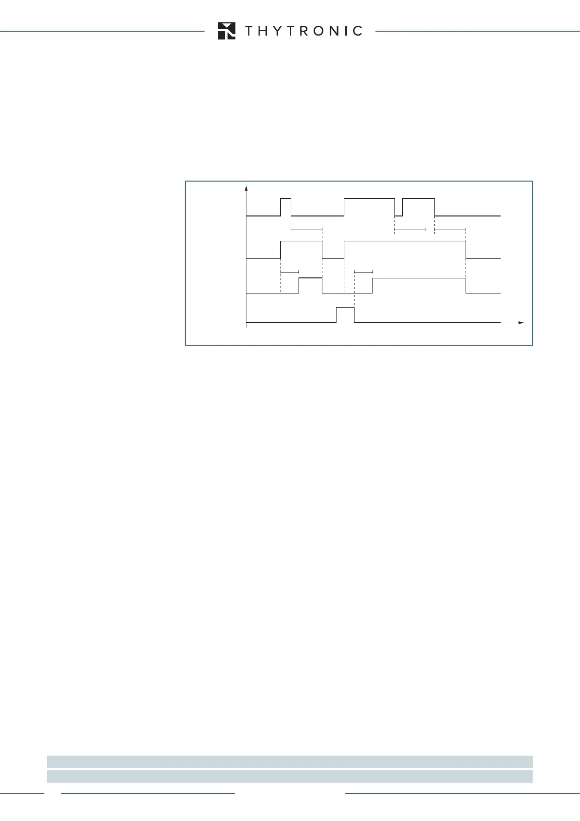
IEC> element residual overcurrent 50N(Calc)/51N(Calc) - Timers
IEC> Start
IEC> Trip
RESET
INPUT
t
EC
t
EC
t
EC>RES
t
EC>RES
t
EC>RES
t
XMR-D EQUIPMENT MANUAL
Ed. 2.9 - 02/2021
 Loading...
